


Power Controller (For Automotive Accessories) Circuit
#power controller
#CD4013
#momentary pushbutton
#automotive accessories
#10A load
#flip-flop
#ignition key
#vehicle power
#accessory switch
#automotive electronics
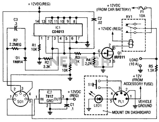
Description: The power controller operates from the vehicle's accessory switch, allowing the load to receive power only when the ignition key is in the "on" position. A momentary pushbutton controls a load of up to 10 A using half of a dual flip-flop (CD4013). While this circuit was initially designed for automotive power management, it may also be suitable for other applications.
The described power control circuit utilizes a CD4013 dual D-type flip-flop, which is an integrated circuit commonly used in digital applications. The circuit is designed to provide a reliable method for controlling electrical loads in automotive settings, ensuring that power is only supplied when the vehicle is in operation.
The momentary pushbutton serves as the user interface, allowing the operator to manually engage the load. When the button is pressed, it triggers the flip-flop, which changes its state and enables the output to drive the load. The flip-flop configuration ensures that the load remains engaged until the ignition is turned off, preventing battery drain when the vehicle is not in use.
The load capacity of this circuit is rated for up to 10 A, making it suitable for various automotive devices such as lights, auxiliary power outlets, or other electronic accessories. The design can be adapted for other applications beyond automotive use, such as in home automation systems or industrial equipment, where control of high-current loads is required under specific conditions.
To implement this circuit, proper attention should be given to the power ratings of the components used, ensuring they can handle the load current without overheating. Additionally, the circuit should include appropriate safety features, such as fuses or circuit breakers, to protect against overload conditions. The use of appropriate wiring and connectors is also essential to maintain the integrity of the circuit and ensure reliable operation.
Overall, this power control circuit exemplifies a practical solution for managing electrical loads with safety and efficiency, while also offering versatility for various applications. Because the power controller is powered from the vehicle`s accessory switch, the load can receive power only when the ignition key is on. Using half of a dual flip-flop (CD4013), a load of up to 10 A is controlled by a momentary pushbutton.
This circuit was originally intended for automotive power control, but could have other applications as well.
The described power control circuit utilizes a CD4013 dual D-type flip-flop, which is an integrated circuit commonly used in digital applications. The circuit is designed to provide a reliable method for controlling electrical loads in automotive settings, ensuring that power is only supplied when the vehicle is in operation.
The momentary pushbutton serves as the user interface, allowing the operator to manually engage the load. When the button is pressed, it triggers the flip-flop, which changes its state and enables the output to drive the load. The flip-flop configuration ensures that the load remains engaged until the ignition is turned off, preventing battery drain when the vehicle is not in use.
The load capacity of this circuit is rated for up to 10 A, making it suitable for various automotive devices such as lights, auxiliary power outlets, or other electronic accessories. The design can be adapted for other applications beyond automotive use, such as in home automation systems or industrial equipment, where control of high-current loads is required under specific conditions.
To implement this circuit, proper attention should be given to the power ratings of the components used, ensuring they can handle the load current without overheating. Additionally, the circuit should include appropriate safety features, such as fuses or circuit breakers, to protect against overload conditions. The use of appropriate wiring and connectors is also essential to maintain the integrity of the circuit and ensure reliable operation.
Overall, this power control circuit exemplifies a practical solution for managing electrical loads with safety and efficiency, while also offering versatility for various applications. Because the power controller is powered from the vehicle`s accessory switch, the load can receive power only when the ignition key is on. Using half of a dual flip-flop (CD4013), a load of up to 10 A is controlled by a momentary pushbutton.
This circuit was originally intended for automotive power control, but could have other applications as well.
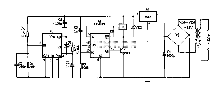
With a CD4013 produce laser light remote control switch
The circuit consists of a 220V AC input connected to a step-down transformer (T), followed by a bridge rectifier (VD3 to VD6) and a three-terminal voltage regulator (block A2) that provides a stable 12V DC output for digital integrated circuits....
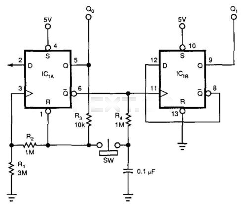
Flip-Flop Debouncer Switch
This circuit utilizes a 74HC74 flip-flop, although any CMOS variant of this component can be employed. IC1A functions as a true/complement buffer. Resistors R1 and R2 ensure that IC1A exits the reset state prior to the clock edge occurrence. Resistor...
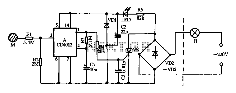
With a CD4013 Touch delay saving lamp production
Diodes VD2 to VD5 and SCR form the main circuit of a touch switch. Resistor R5 and diode VD1 create a power supply circuit that outputs approximately 12V DC, which is utilized for a manifold A application. The circuit incorporates...
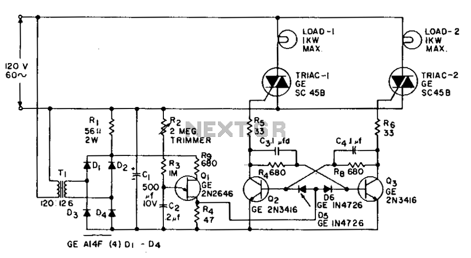
1 Kw flip-flop flasher circuit
This application involves a static switch circuit where the control logic is implemented using a flip-flop, which is driven by a unijunction transistor. The flashing rate of the circuit can be adjusted, ranging from approximately 0.1 seconds to a 10-second...
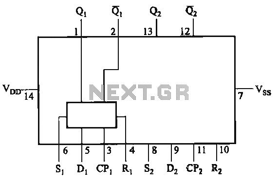
CD4013 circuit
The CD4013 is a dual D flip-flop that operates on the rising edge of the clock signal. Its internal block diagram and pin configuration are provided. This device is part of the standard model C043 and the GB model CC4013....
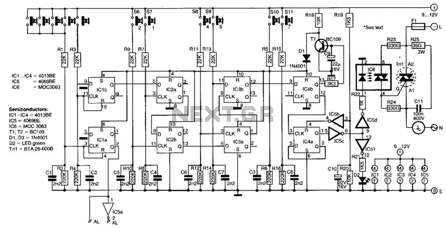
6 Digit Coded Ac Power Switch Circuit
This switch utilizes four CD4013BE dual flip-flops, an inverter, and an optoisolator to control a triac, allowing it to switch a 25-A AC load current. A standard 4x3 telephone keypad is employed for entering a 6-digit code. In the event...
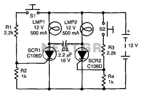
Flip-Flop Independent Lamp Driver
Assume first that SCR1 is on and SCR2 is off, allowing capacitor CI to be fully charged, with its LMP2 end positive. The state of the circuit can be altered by pressing switch S2. When SCR2 turns on, it capacitively...
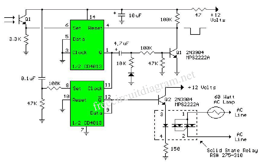
Toggle Flip Flop Laser Pointer Using CD4013
The circuit below is similar to the one above but can be used with a laser pointer to toggle the relay rather than a push button. The IR photo transistor Q1 (Radio Shack 276-145A) or similar is connected to the...
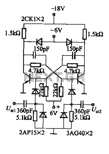
Practical flip-flop circuit
A flip-flop circuit with a memory function for pulse signals. It features two stable states: one where transistor VTi is off and VTZ is conducting, and another where VTi is conducting and VT2 is off. An external signal is sufficient...