
cap humidity sensor circuit
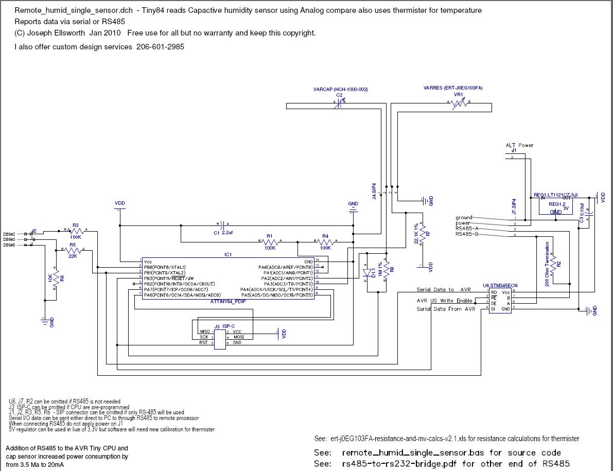
The circuit design utilizes a microcontroller to read capacitance changes, allowing for effective humidity measurement without the need for complex components or expensive sensors. The core principle relies on the time it takes to charge a capacitor through a resistor, with the diode ensuring rapid discharge to maintain accuracy. The microcontroller's ability to measure time in a tight loop minimizes variability caused by interrupt service routines, leading to more consistent readings.
Calibration is a critical aspect of this design, especially considering the inherent variances in low-cost sensors. By using known humidity solutions for calibration, the system can effectively translate capacitance changes into accurate humidity percentages. The design also accommodates the need for field recalibration, which is essential for maintaining measurement accuracy over time, especially in environments where sensor drift is a concern.
The incorporation of RS485 and TTL serial communication enhances the versatility of the circuit, allowing for integration with various digital systems. The design considerations regarding power connections highlight the importance of preventing potential damage to connected devices, ensuring reliability in practical applications. Overall, this circuit presents a robust solution for humidity sensing, balancing cost, accuracy, and ease of use in field conditions.This document describes how to read a capacitive humidity sensor directly from a micro controller using 1 resistor, 1 diode the sensor and two IO lines. It does this without an ADC by measuring the amount of time it requires to charge the capacitor through a resistor until the charge level is sufficient to register as logic 1.
As the humidity chan ges the capacitance changes which changes the time required to charge the circuit. We measure the time in a tight processor loop and average the readings to reduce hysteresis. The readings are calibrated to two known humidity points using aqueous salt solutions. The calibration allows simple conversion to percentages which can then be used internally or shipped out through a digital network such as RS422. Most humidity sensors change consistently at a given capacitance change per 1% humidity change so the humidity can be calculated as a direct correlation to capacitance changes.
While this circuit was designed specifically to support humidity sensors it should work the same with any circuit which uses a variable capacitor that predictably changes across it`s set of input such as stress gauges. It can be extended with lookup tables to support devices which do not deliver a linear ramp across it`s operating range.
I ran out of ADC pins and didn`t want to install a multiplexer or external ADC for my 3 humidity sensors. I was tired of paying $15 to $35 each for humidity sensors like the vout HM1500 or the digital Sensirion SHT75.
In addition I found that many of the vout and freq out units had drifts exceeding 10% after 1 year in our application. My other issue is that the more sophisticated vout sensors keep getting model changes which requires design changes for us while the base level cap sensors remained the same and reliable.
I needed an adequate solution that was cheaper and could be easily field re-calibrated. I looked at many of the 555 circuits but they seemed complex with lots of components which could have thermal drift. I wanted something that would be easy to integrate into remote mounted circuits dozens to hundreds of feet away while keeping costs low.
My design is based on reading the capacitance variance directly from the micro controller and have been reasonably satisfied with the results. The cheap sensors like the HCH-1000-002 and the HS1101 do not come pre-calibrated and I found over a 10% variance from sensor to sensor so calibration must be built into the software.
Due to high rates of drift I needed a easy way to re-calibrate in the field. After a very primitive calibration run, I ran a quick check using a sodium chloride (table salt) calibration solution my readings after averaging ran +- 1. 5% of the 75. 3% expected which is within the hysteresis ratings of the HCH-1000-002 sensor. Improved algorithms with more sophisticated averaging would make this more accurate. The circuit is descried at and is free to use. It basically uses a two digital IO lines one as a charge and the other as a sense. We charge the capacitor circuit through a resistor with a diode for fast drain back. We feed the sense line from the cap back to the micro controller. The capacitor is fully drained before the feed line is activated. We measure the time it requires for sense to convert from a logic low to logic high in a tight loop with a counter.
Once the transition high on sense occurs the feed line is set to low which re-drains the sensor cap. As the capacitor value rises or falls with humidity the count value rises and falls proportionately. We measure the count in a tight loop because we found the variables in interrupt service for the timer caused undesirable variability in the readings. · Average last reading into last 7 (N). Calculate the slope of change as far as count increments per percentage of humidity then convert then this into actual percentage change and add it to the low calibration point or subtract from low calibration point if below.
· The circuit acts like an AC wave because PD. 6 only remains on long enough for PD. 5 to read as on then PD. 6 drops which drains the capacitor. · Diode discharges sensor fast when PD. 6 drops. Use low forward voltage drop diode to minimize residual charge that must drop through the resistor. We found a good count value with reasonable resolution using a 20 Meg feed capacitor on the HCH-1000-002 and a 40 Meg for the HS1101. One concern was that the transition from logic low to logic high is defined as a range so I thought it would be sloppy.
I checked this with no cap in circuit and by using a fixed capacitor. When the variable cap is removed from the circuit it consistently takes 18 cycles to charge the circuit whereas when the cap is present it ranges from 1080 to 1300. When we place a fixed capacitor in circuit it stays the same within a 6 or so cycles and normally stays within 1 cycle from test to test.
I interpret this as a consistent transition voltage from low to high on sense which is basically doing the same thing as a analog comparator. A analog comparator would probably be more accurate but I actually saw comparable variability up/down 1.
5 to 3% when reading the vout HM1500 sensors through the ADC and had to run an averaging algorithm anyway. The difference is a sensor which is 4 times cheaper. This design is second generation, Instead of strict logic transition it uses a voltage divider to provide a reference voltage and then uses on CPU analog comparator sense charge rate.
· It uses the ACI (Analog Comparator) interrupt and the AVR 16 bit timer / counter to accumulate the time for the RC constant. The speed of the 20 Mhtz CPU combined with the speed of the counter and higher threshold value allowed the resistance on the feed resistor R7 to be reduced from 20 Meg to 1 Meg and still deliver higher resolution with faster reads · This circuit provides output via RS485 or a TTL serial that is compatible with most laptops.
When using the RS485 circuit you must disconnect the normal power J1 as the power is fed in over the RS485 connector J2. The PC compatible serial output is on J2. It does not conform to RS232 specs but it has worked on every laptop I have used. · When using the RS232 connector ensure that you connect the ground to the power connectors J2 before applying power in.
Otherwise the circuit will operate through the ground connection to the serial port. This is not a problem when the circuit draws very little power but is very bad practice because a high current short could burn out traces on the laptop or PC mother board. Where this is a risk a 30Ma fuse should be added on the RS232 ground leg to avoid expensive damage to your development computer.
· On surprising result from this circuit is that the analog comparator result does not seem as food additives. 🔗 External reference
Related Circuits
Long-distance infrared transmitter circuit diagram. This simple circuit offers a considerable range by utilizing three infrared transmitting LEDs (IR1 through IR3) in series to enhance the radiated power. To further improve directivity and power density, the IR LEDs can...
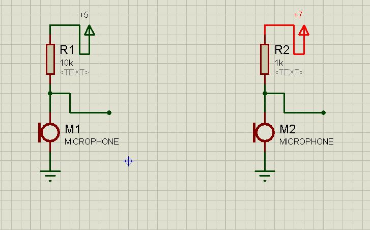
How can one theoretically determine the output of a capacitor microphone, or estimate it without testing? For instance, in the following circuits, what is the output of each? The output of a capacitor microphone, also known as a condenser microphone,...
A light/dark sensing circuit is highly useful and versatile for various renewable energy projects, including automatic lighting and security systems. The article on Light Dependent Resistors (LDR) explains how an LDR can be employed in simple circuits to control...
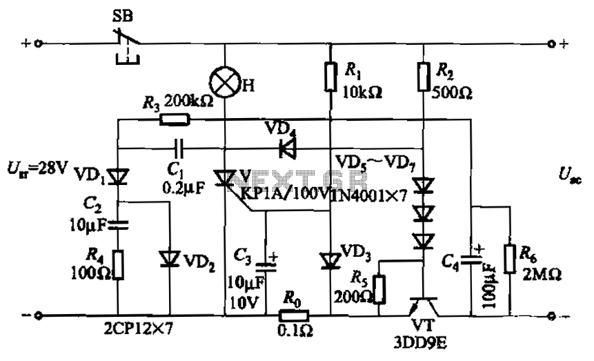
Capacitor C3 is used to determine the cutoff power, specifically the voltage threshold (VT cutoff), which influences the delay time selection. The schematic includes a reset button, SB, that is utilized to reset the system after a failure has...
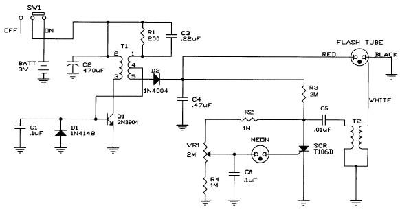
Caution! This strobe light circuit operates on 220V, making measurements and experiments extremely hazardous, even after disconnecting it from the mains. The strobe light circuit is designed to produce high-intensity flashes of light at specified intervals. It typically consists...
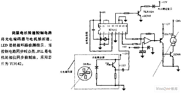
The servo motor speed control circuit connects the photoelectric encoder to the motor shaft. The LED serves as an indicator light for the phase-locked loop (PLL) detection, illuminating when the control circuit is synchronized. The PLL employs a phase...