
Strobe Light Circuit
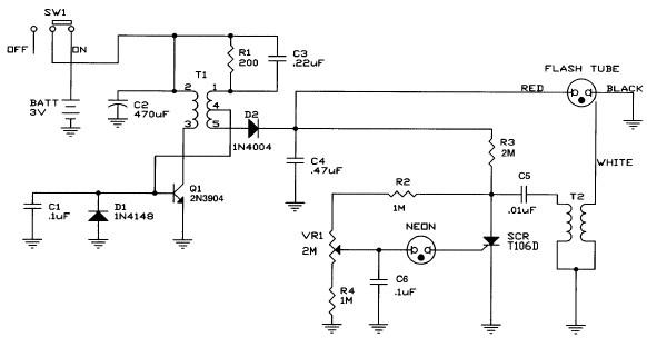
The strobe light circuit is designed to produce high-intensity flashes of light at specified intervals. It typically consists of a power supply section, a control circuit, and a strobe light element. The power supply converts the 220V AC mains voltage into a suitable DC voltage, which powers the control circuit and the strobe light.
The control circuit may include components such as a timer, a microcontroller, or a simple oscillator that determines the frequency and duration of the light flashes. Safety features should be implemented to prevent electric shock, including proper insulation, fuse protection, and the use of relays to isolate high voltage components from user-accessible parts.
The strobe light itself can be an incandescent bulb, LED array, or a xenon flash tube, depending on the desired brightness and application. The design must ensure that all components are rated for the voltage and current they will encounter during operation.
It is essential to follow safety guidelines when working with high-voltage circuits, including using insulated tools, wearing protective equipment, and ensuring that the circuit is de-energized before making any adjustments or measurements. Proper grounding and circuit layout will also mitigate risks associated with electrical shock and equipment damage.Attention! This strobe light circuit is connected to 220V, so measurements and experiments are very dangerous even after unplugging it from the mains. P1 p.. 🔗 External reference
Related Circuits
A simple preamplifier circuit is often required, utilizing a few components for ease of construction. This circuit employs an operational amplifier, specifically the Motorola TCA5550, which features a dual amplifier configuration. It provides outputs for adjusting volume, balance, treble,...
The following circuit illustrates how to build a variable DC power supply circuit. This circuit is based on the 7805 IC. Features: other output is ... The variable DC power supply circuit utilizing the 7805 integrated circuit (IC) is designed...
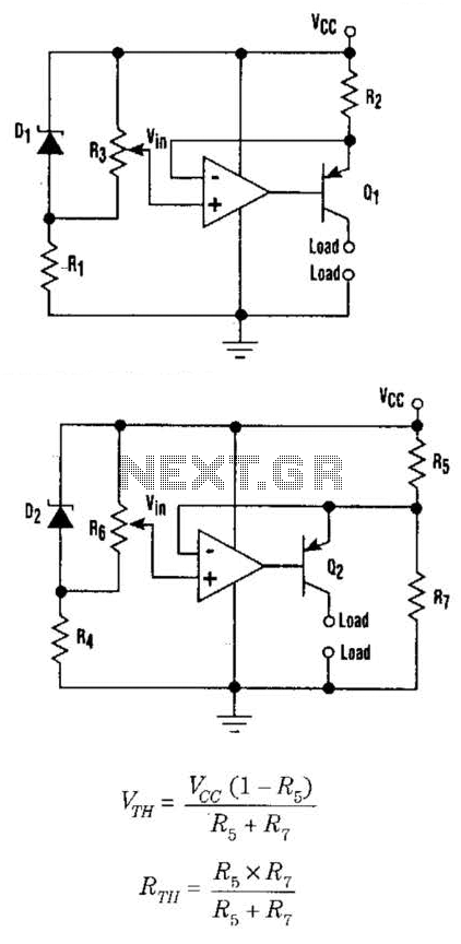
This setup can function as a cost-effective current source with an output accuracy of 1%. However, the voltage offset can activate the current source even when Vqq equals Vin. Modifying the configuration of Figure 1 can resolve the issue...
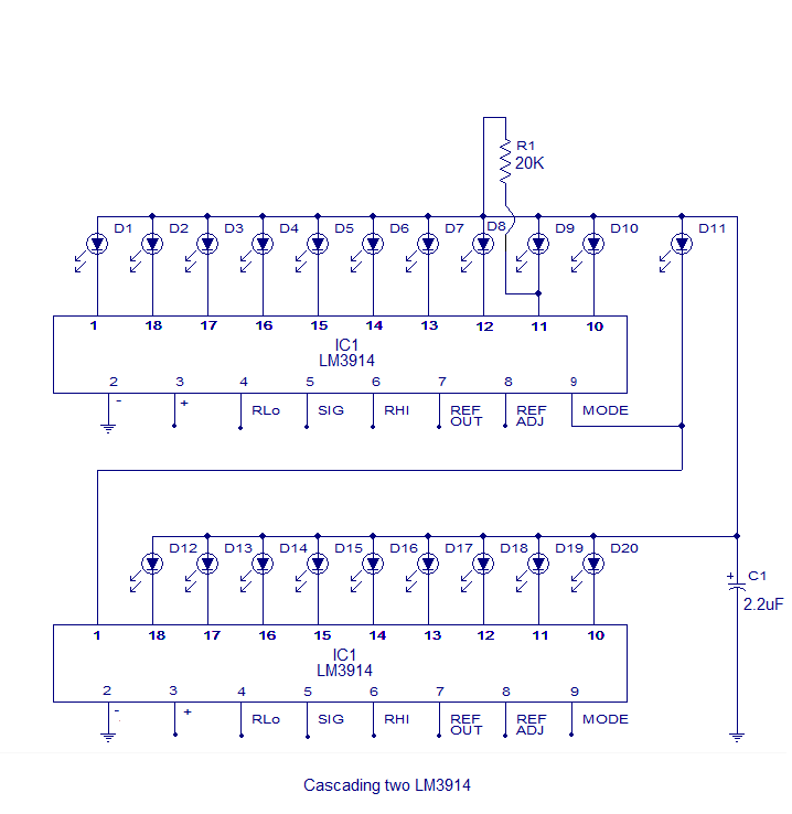
The core of this circuit is the LM3914 from National Semiconductor. The LM3914 is capable of sensing voltage levels and can drive a display of 10 LEDs in either dot mode or bar mode. The selection between bar mode...
A DC supply of +5 V is obtained from a 230 V AC source. This power supply is utilized by other circuit blocks. A pulse generator operating at a specific frequency generates clock pulses. These clock pulses are counted...
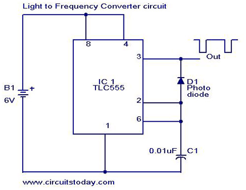
A simple light-to-frequency converter circuit with a diagram and schematic. It is used as a light intensity measurement circuit. The design utilizes the TLC555, a CMOS version of the NE555 timer IC. The light-to-frequency converter circuit is designed to convert...