
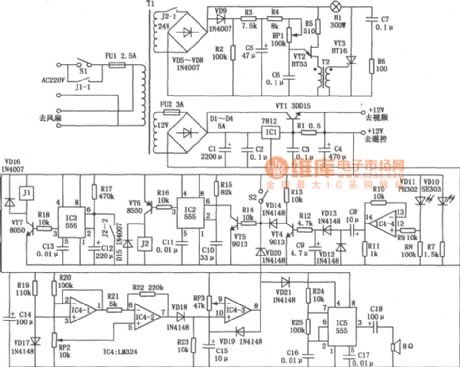
Servo motor speed control circuit
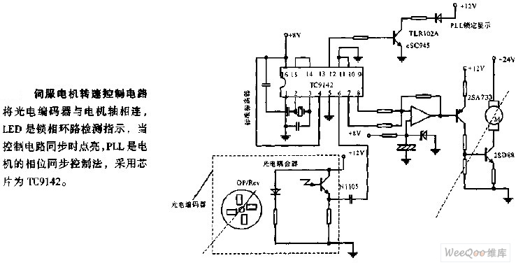
The servo motor speed control circuit is designed to regulate the speed of a servo motor by implementing a feedback mechanism that utilizes a photoelectric encoder. This encoder is mechanically linked to the motor shaft, providing real-time position and speed data to the control system. The integration of the encoder allows for precise control of motor speed, ensuring that the motor operates at the desired setpoint.
The phase-locked loop (PLL) is a critical component of this circuit, serving to synchronize the motor's operation with the input signal. The TC9142 chip is utilized for its capabilities in phase detection and control. This chip processes the feedback from the encoder, comparing the actual motor speed to the desired speed. If a discrepancy is detected, the PLL adjusts the control signals sent to the motor, thereby achieving synchronization.
The LED indicator plays an essential role in providing visual feedback regarding the status of the PLL. When the control circuit achieves synchronization, the LED illuminates, signaling that the motor is operating correctly within its designated parameters. Conversely, if the LED is off, it may indicate a loss of synchronization, prompting further investigation into the system's performance.
In summary, this servo motor speed control circuit combines the functionalities of a photoelectric encoder, a PLL for phase synchronization, and an LED indicator to create an efficient and effective motor control solution. The use of the TC9142 chip enhances the circuit's ability to maintain precise control over motor speed and performance, making it suitable for various applications in automation and robotics.The servo motor speed control circuit connects the photoelectric encoder with the motor shaft, the LED is the indicator light of the PLL detection, it turns on when the control circuit is synchronous. The PLL is the phase synchronous control method of the electrical moter, it uses the chip of TC9142..
🔗 External reference
Related Circuits
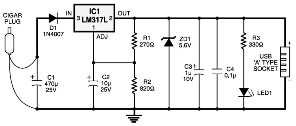
A USB port is capable of supplying more than 100 mA of continuous electric current at 5V to peripherals connected to the bus. This feature allows a USB port to power 5V DC-operated small electronic devices without issues. Many...
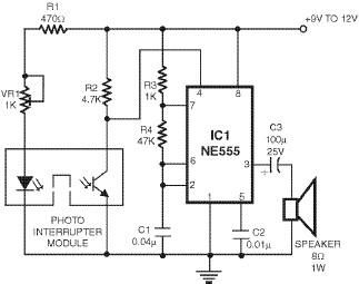
This smoke detector utilizes a 555 timer circuit along with common electronic components. The photo interrupter module serves as the smoke detection element, while the 555 timer is configured in astable mode to function as an audio frequency oscillator,...
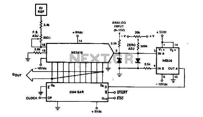
The time IO-bit conversion operates at 3.3 MHz with a clock signal. This converter utilizes a 2504 12-bit register in successive approximation mode, where the conversion signal for the short-cycle end is derived from the first bit utilized in...
This circuit utilizes a dual operational amplifier (TL082) to create a voltage-controlled oscillator (VCO). The specified component values allow the output frequency to range from 100 Hz to 10 kHz when the input control voltage is between 0.05 and...
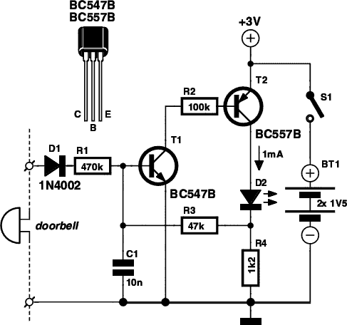
If you are expecting an important visitor but need to step out for a moment, an electronic doorbell memory can be useful to check whether someone rang while you were away. While it cannot confirm if it was the...
Select a free schematic drawing software that resembles the two mentioned. There have been discussions regarding circuit drawing software. Fritzing is favored, although it lacks certain components, such as the RS232 component. There is a request for feedback on...
Warning: include(partials/cookie-banner.php): Failed to open stream: Permission denied in /var/www/html/nextgr/view-circuit.php on line 713
Warning: include(): Failed opening 'partials/cookie-banner.php' for inclusion (include_path='.:/usr/share/php') in /var/www/html/nextgr/view-circuit.php on line 713