
car tracking device circuit diagram
The car tracking device operates on the principle of radio frequency transmission and reception. The tank circuit, formed by C2 and L1, is critical for generating a resonant frequency that matches the frequency of the transmitter, ensuring efficient signal transmission. The coupling capacitor C3 plays a vital role in linking the transmitter to the antenna, which can be tailored to the specific application requirements, whether through a telescopic design for portability or a simple hookup wire for ease of construction.
On the receiver side, the signal tuning is accomplished through the combination of C4 and L2, which filters and amplifies the incoming signal before it reaches the 741 operational amplifier. This amplifier is responsible for further processing the signal, amplifying it to a level suitable for detection and interpretation by the LED indicators. The five LEDs provide a visual representation of the signal strength, enabling users to ascertain the proximity and direction of the tracked object.
During the tuning process post-construction, it is essential to ensure that the transmitter is adjusted correctly so that the maximum number of LEDs illuminate, indicating optimal signal reception. The variable resistor Rv2 allows fine-tuning of the receiver's sensitivity, ensuring that the strongest signal is registered when the receiver's antenna is aligned with the transmitter. This careful calibration is crucial for effective operation of the tracking device, enhancing its reliability and performance in real-world applications.Tank circuit C2 and L1 is used to tune the transmitter. The antenna is coupled to the transmitter through C3 and must be a telescopic antenna or a length of hookup wire. At the receiver, the incoming signal is tuned by C4 and L2 before being passed on to the 741 IC. To find the object using this car tracking device is use a visual indications wit h 5 LEDs which indicate the signal strength. After build, the car tracking device ( receiver and transmitter ) will need to be tuned. We need to tune the transmitter until all of the receiver`s LEDs light and adjust Rv2 until you get a maximum strength reading only when the receiver`s antenna is pointed directly at the transmitter. 🔗 External reference
Related Circuits
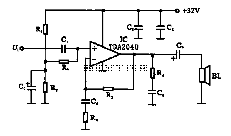
An integrated power amplifier TDA2040 is used in an OTL (Output Transformer-Less) power amplifier circuit, which operates with a +3V single supply as the working voltage. This circuit has a voltage gain of 30 dB (approximately 32 times magnification),...
This is a useful instrument for workshops. The standard of the produced frequencies is 10 to 1. The basic frequency is produced by a crystal with high accuracy. The circuit consists of the oscillator, around the crystal and the...

The circuit below demonstrates the generation of a single positive pulse that is delayed in relation to the trigger input time. It is similar to a previously described circuit but utilizes two stages, allowing for control over both the...
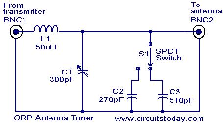
Low power (3 to 30 MHz) transmitters constructed by amateur radio operators are commonly referred to as QRP transmitters. A well-tuned antenna is essential for these transmitters; if the impedance is not properly matched, the output will be minimal...
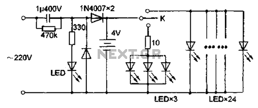
The circuit diagram depicted in Figure 5 illustrates a system for charging a lead-acid battery using 220V AC power. The circuit employs a capacitor, buck converter, and diode rectifier for this purpose. A red LED indicates the charging status....
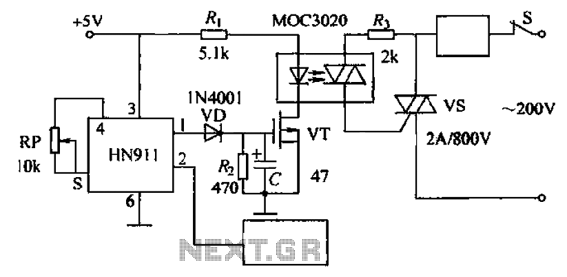
Automatic door control circuit diagram. It utilizes a pyroelectric infrared detection module, HN911, for human motion detection. A variable resistor (potentiometer) is used to adjust the delay time controlled by a transistor (VT). An optocoupler (MX: 3020) provides AC...