


RJ45 Network card to IR communication
#IR communication
#opto-isolation
#data transmission
#network card
#infrared diodes
#file transfer
#RJ45
#computer interface
#wireless communication
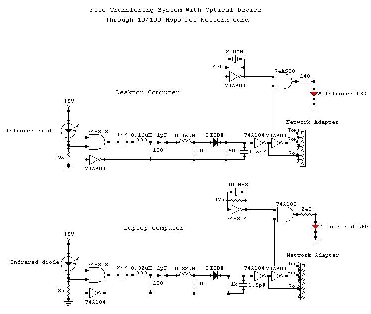
Description: This system consists of two opto-isolated circuits that facilitate data transmission via an infrared network device between two computers. For instance, a user can transfer files from a desktop computer to a laptop computer without the use of cables, utilizing infrared diodes. A connection must be established to the 10/100 Mbps network card of both computers using a very short network cable (less than 10 cm). One end of the cable must be stripped to enable wire connections. Care must be taken during the connections; the Tx+ output of one network card must be connected to the Rx+ input of the other card using the cable, and the same applies to the Tx- and Rx- connections. The circuits require two voltage sources; it is recommended to use a 9V battery and the +5V output from the power supply of the desktop computer. The ground of the power supply should be connected to the circuit ground. For the laptop computer, a 9V battery and a 4.5V battery are suggested. All digital components should belong to the 74H series due to their short response times (less than 2.5 ns). All GND pins of the logic integrated circuits must be connected to the circuit ground, and their Vcc pins must be connected to the appropriate +Vcc of their respective circuits.
This system employs two opto-isolated circuits to enable wireless data transfer between computers through infrared technology. The use of infrared diodes allows for a cable-free connection, streamlining the file transfer process. The connection to the 10/100 Mbps network cards requires careful preparation of a very short network cable, ensuring that one end is stripped for proper wiring.
In terms of connections, the Tx+ output from one network card must be linked to the Rx+ input of the opposing card, and similarly, the Tx- must connect to the Rx- of the other card. This configuration is crucial for maintaining the integrity of the data transmission. The power supply setup is also critical; utilizing a 9V battery in conjunction with the +5V output from the desktop's power supply ensures that the circuits function effectively. It is essential to ground the power supply to the circuit ground to avoid potential issues with signal integrity.
For the laptop, a combination of a 9V battery and a 4.5V battery is recommended, providing the necessary voltage levels for the opto-isolated circuits. The requirement for the use of 74H series digital components is significant, as these components are designed for rapid response times, which is vital for maintaining efficient data transfer rates. Proper grounding of all GND pins and correct Vcc connections for each logic integrated circuit is necessary to ensure reliable operation of the system.
Overall, this schematic enables a straightforward yet effective method for wirelessly transmitting data between computers, leveraging the advantages of infrared technology and careful circuit design.This system, composed of two opto-insulated circuits, allows the data transmission per infra-red network device between two computers. For example, someone can transfer his files starting from his desktop computer to his laptop computer without using any cable.
How By using infra-red diodes. We have to connect a circuit to the 10/100 Mbps network card of both computers by using a very small network cable (can be smaller than 10 cm). One of the two extremities of the cable must be removed to allow the wire connections. We must pay attention when we do the connections. The Tx+ output of any network card is connected to the input of the Rx+ of the other with the cable. It`s the same way for the Tx- and the Rx-. We have to supply the circuits with two sources of voltage. I recommend to use a 9V battery and the +5V output of the power supply for the desktop computer. The ground of the power supply must be connected to the ground of the circuit. For the laptop computer, I recommend to use a 9V battery and the 4. 5V battery. All digital components must be of the 74H series because these have short response times (less than 2. 5 ns). All the GND pins of the logic integrated circuits must be connected to the ground of their circuit and their Vcc pin must be connected to the +Vcc of their circuit.
This system employs two opto-isolated circuits to enable wireless data transfer between computers through infrared technology. The use of infrared diodes allows for a cable-free connection, streamlining the file transfer process. The connection to the 10/100 Mbps network cards requires careful preparation of a very short network cable, ensuring that one end is stripped for proper wiring.
In terms of connections, the Tx+ output from one network card must be linked to the Rx+ input of the opposing card, and similarly, the Tx- must connect to the Rx- of the other card. This configuration is crucial for maintaining the integrity of the data transmission. The power supply setup is also critical; utilizing a 9V battery in conjunction with the +5V output from the desktop's power supply ensures that the circuits function effectively. It is essential to ground the power supply to the circuit ground to avoid potential issues with signal integrity.
For the laptop, a combination of a 9V battery and a 4.5V battery is recommended, providing the necessary voltage levels for the opto-isolated circuits. The requirement for the use of 74H series digital components is significant, as these components are designed for rapid response times, which is vital for maintaining efficient data transfer rates. Proper grounding of all GND pins and correct Vcc connections for each logic integrated circuit is necessary to ensure reliable operation of the system.
Overall, this schematic enables a straightforward yet effective method for wirelessly transmitting data between computers, leveraging the advantages of infrared technology and careful circuit design.This system, composed of two opto-insulated circuits, allows the data transmission per infra-red network device between two computers. For example, someone can transfer his files starting from his desktop computer to his laptop computer without using any cable.
How By using infra-red diodes. We have to connect a circuit to the 10/100 Mbps network card of both computers by using a very small network cable (can be smaller than 10 cm). One of the two extremities of the cable must be removed to allow the wire connections. We must pay attention when we do the connections. The Tx+ output of any network card is connected to the input of the Rx+ of the other with the cable. It`s the same way for the Tx- and the Rx-. We have to supply the circuits with two sources of voltage. I recommend to use a 9V battery and the +5V output of the power supply for the desktop computer. The ground of the power supply must be connected to the ground of the circuit. For the laptop computer, I recommend to use a 9V battery and the 4. 5V battery. All digital components must be of the 74H series because these have short response times (less than 2. 5 ns). All the GND pins of the logic integrated circuits must be connected to the ground of their circuit and their Vcc pin must be connected to the +Vcc of their circuit.
Carrier Current Transmitter For Data Transmission
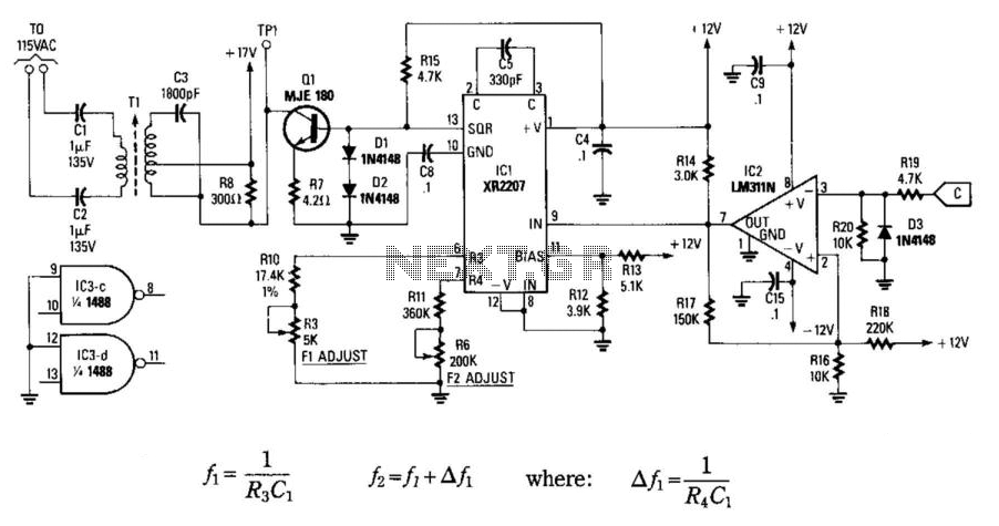
In this circuit, data at input C is amplified by IC2 and then fed to modulator IC1. IC1 generates two frequencies, depending on the values of C5, I10, R5, Rn, and R6. The frequency f1 is generated if pin 9...
IR InfraRed Communication circuit
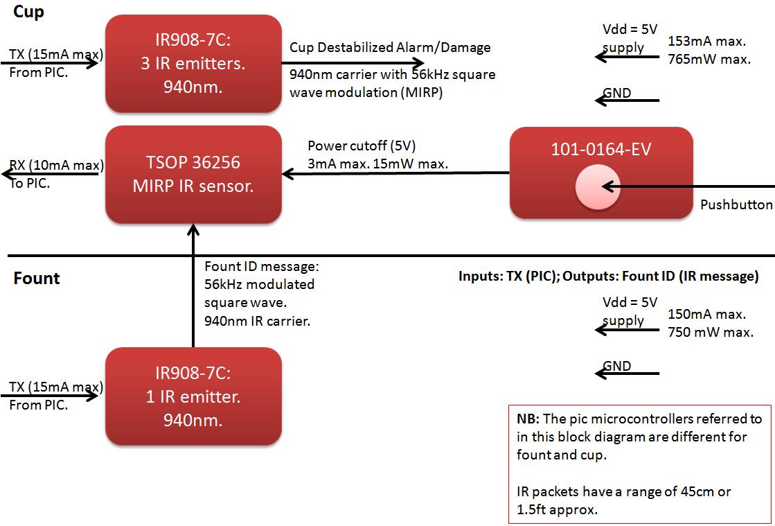
The founts must notify the server when the cup is taken from the fount or when the opponent's cup is poured into the team's cup. The implementation of the actual pouring action is at the discretion of the team. If...
Wireless Communication Hobby Projects
Another method of testing the received signal strength on a Symphony-based wireless network is with a homebrew signal meter. The National LMX2240 Intermediate Frequency Receiver has a pin called "RSSI Out." RSSI stands for Relative Signal Strength Indicator and provides...
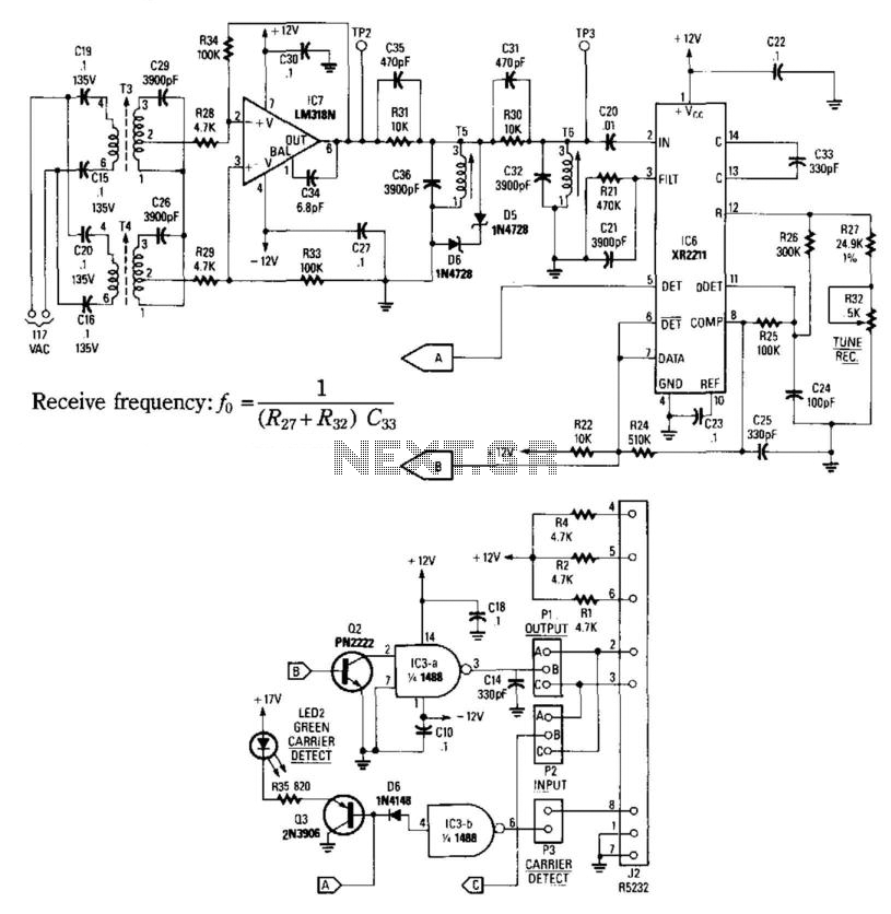
Carrier-Current Receiver For Data Transmission
This receiver consists of an input network, amplifier IC7, FSK PLL detector IC8, and output amplifier/interface circuits Q2, Q3, IC3A, and IC3B, which include a 1488 Quad RS232 line driver for the carrier-current signal. The tuned amplifier IC7 amplifies this...
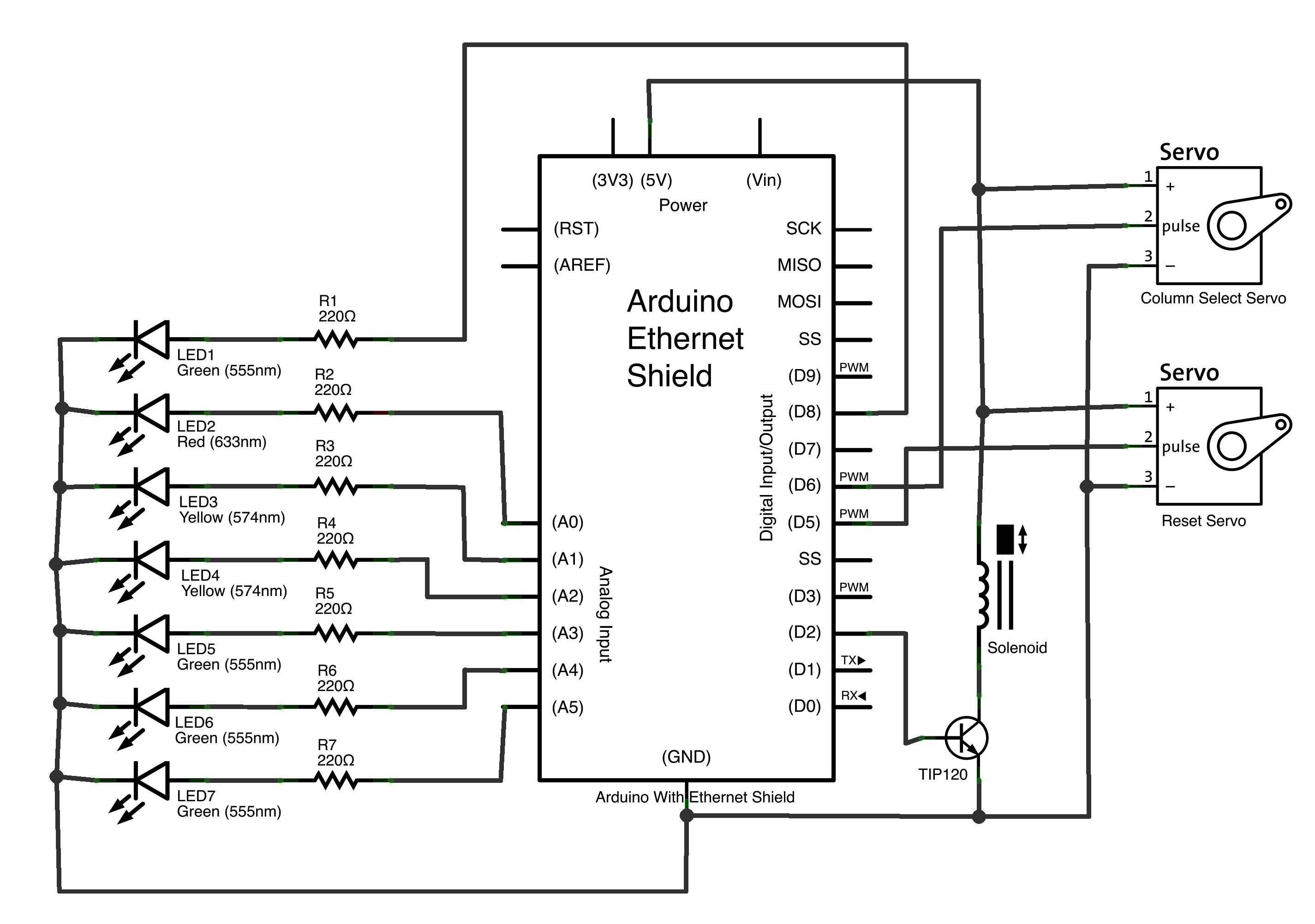
connect 4000
The objective of this project was to investigate the wireless linkage of objects, locations, and individuals. Initial discussions revolved around the intended use of the project—whether for private or public purposes—and the number of participants involved. Considerations included the choice...
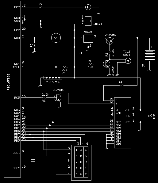
Remote IR controller
This unit provides 2-way IR communications using a numeric keypad and an LCD display. Data is sent and received in ASCII with no regard to what the data means to any particular device. The ASCII data still needs some form...
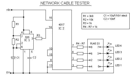
Network RJ45 Cable Tester Circuit
This is a multifunction RJ45 network cable tester designed for testing network cables (RJ45) and telephone cables (RJ11). It is cost-effective and user-friendly. The tester determines whether a network cable is a crossover or straight type by illuminating a yellow...
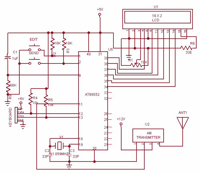
Wireless Data Communication system
This project is used to communicate or transmit a text message from one place to another place through wireless. The text message is encrypted by using the Microcontroller and the encrypted message was transmitted through wireless. At the receiver end...