


Video Switch Circuit Schematic Diagram
#video switch
#MAX454
#multiplexer
#amplifier
#signal path
#crosstalk prevention
#video signal
#monitor display
#ground plane
#noise reduction
Description: A video switcher circuit is required to display multiple sources on a single monitor. The circuit schematic below features the MAX454, which serves as the core component of this video switcher. The MAX454 is a video multiplexer-amplifier manufactured by MAXIM Semiconductor. It is crucial to carefully design the video signal path around this chip. A ground plane can be inserted between video signal channels to minimize crosstalk and noise interference. The chip must be directly soldered to the PCB. Additionally, a CD4017 sequencer is included to drive the channel indicators (LED1-LED4). The sequencer decodes 2-bit binary data using D1 to D4 to address the MAX454 multiplexer. The outputs from this sequencer also control the indicators.
The video switcher circuit is designed to facilitate the selection of multiple video inputs for display on a single output monitor. The MAX454, a key component, functions as both a multiplexer and an amplifier, ensuring that video signals are processed with minimal degradation. It is important to maintain a well-planned signal path around the MAX454 to optimize performance. The inclusion of a ground plane between the signal channels is a recommended practice to reduce crosstalk and interference, which can adversely affect video quality.
The CD4017 decade counter serves as a sequencer that controls the activation of channel indicators, represented by LEDs (LED1-LED4). This sequencer operates by decoding a 2-bit binary signal, allowing for straightforward selection of the desired video channel. The outputs from the CD4017 not only indicate which channel is currently active but also facilitate the switching of the MAX454 multiplexer to the corresponding video input.
In designing the PCB for this circuit, it is essential to ensure that the MAX454 is soldered directly to the board to maintain signal integrity and reduce the potential for noise introduction. Proper layout techniques, including the use of ground planes and careful routing of signal traces, will enhance the overall performance of the video switcher circuit, making it suitable for applications requiring reliable video source selection.Video switcher circuit is needed to display more than one display in one monitor. Take a look at below circuit schematic : MAX454 is the core of this video. It is a video multiplexer-amplifier assembled by MAXIM Semiconductor. Pay attention when designing the video signal path around this chip. Track of ground plane can be inserted between video signal channels to prevent crosstalk and noise interference. The chip should directly soldered to the PCB. A CD4017 sequencer which drive the channel indicators (LED1-LED4) can be seen here. The output will decode 2 bit binary data by D1. D4 to address MAX454 multiplexer. The output of this sequencer also drives the indicators.
The video switcher circuit is designed to facilitate the selection of multiple video inputs for display on a single output monitor. The MAX454, a key component, functions as both a multiplexer and an amplifier, ensuring that video signals are processed with minimal degradation. It is important to maintain a well-planned signal path around the MAX454 to optimize performance. The inclusion of a ground plane between the signal channels is a recommended practice to reduce crosstalk and interference, which can adversely affect video quality.
The CD4017 decade counter serves as a sequencer that controls the activation of channel indicators, represented by LEDs (LED1-LED4). This sequencer operates by decoding a 2-bit binary signal, allowing for straightforward selection of the desired video channel. The outputs from the CD4017 not only indicate which channel is currently active but also facilitate the switching of the MAX454 multiplexer to the corresponding video input.
In designing the PCB for this circuit, it is essential to ensure that the MAX454 is soldered directly to the board to maintain signal integrity and reduce the potential for noise introduction. Proper layout techniques, including the use of ground planes and careful routing of signal traces, will enhance the overall performance of the video switcher circuit, making it suitable for applications requiring reliable video source selection.Video switcher circuit is needed to display more than one display in one monitor. Take a look at below circuit schematic : MAX454 is the core of this video. It is a video multiplexer-amplifier assembled by MAXIM Semiconductor. Pay attention when designing the video signal path around this chip. Track of ground plane can be inserted between video signal channels to prevent crosstalk and noise interference. The chip should directly soldered to the PCB. A CD4017 sequencer which drive the channel indicators (LED1-LED4) can be seen here. The output will decode 2 bit binary data by D1. D4 to address MAX454 multiplexer. The output of this sequencer also drives the indicators.
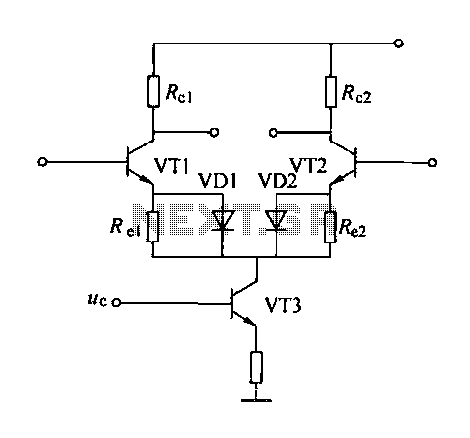
Emitter negative feedback differential amplifier gain control circuit
A controllable gain amplifier functions as an automatic gain control circuit within the execution unit. The primary methods for controlling the amplifier's gain involve two approaches: one is by adjusting certain parameters of the amplifier itself, such as emitter current,...
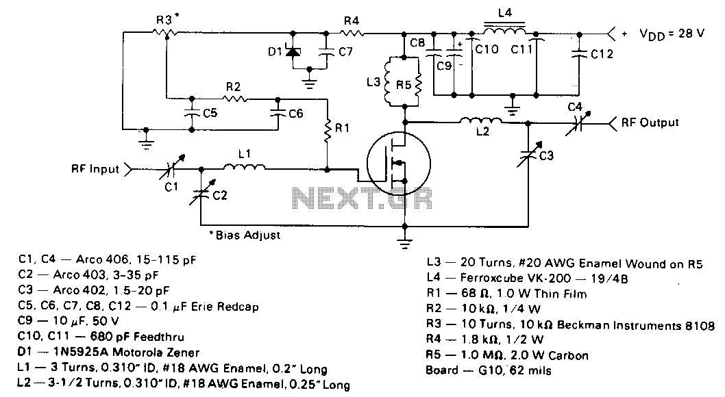
5W-150mhz-amplifier
This circuit employs the MRF123 TMOS power FET. The MRF134 is a high-gain FET that may exhibit instability at both VHF and UHF frequencies. A 68-ohm input loading resistor has been used to improve stability. This amplifier achieves a gain...
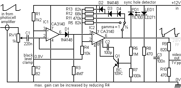
Adding sync pulses to the video signal
This section provides details for generating a composite video output signal from a camera to drive an external monitor. The circuit, designed by Peter Smith, integrates a DC-restorer, a switchable gamma corrector, and a video/sync mixer using a photodiode and...
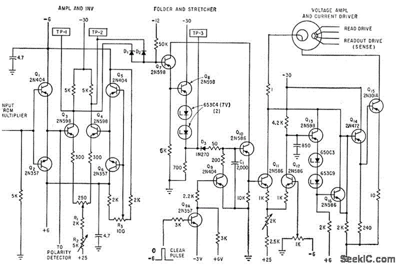
INVERTER_AND_PULSE_STRETCHER
The circuit samples the output of a multiplexer and provides the necessary current for driving a transfluxor in an analog-to-digital converter that generates a six-bit binary Gray code. -N. Aron and C. Granger, Analog-To-Digital Converter Uses Transfluxors, Electronics, 35:20, p...
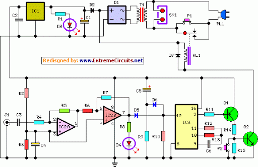
Amplifier Timer Circuit Schematic
This circuit turns off an amplifier or any other device when it remains idle for 15 minutes. It is powered by the amplifier's tape output.
The described circuit functions as an automatic power management system, designed to enhance energy efficiency by...
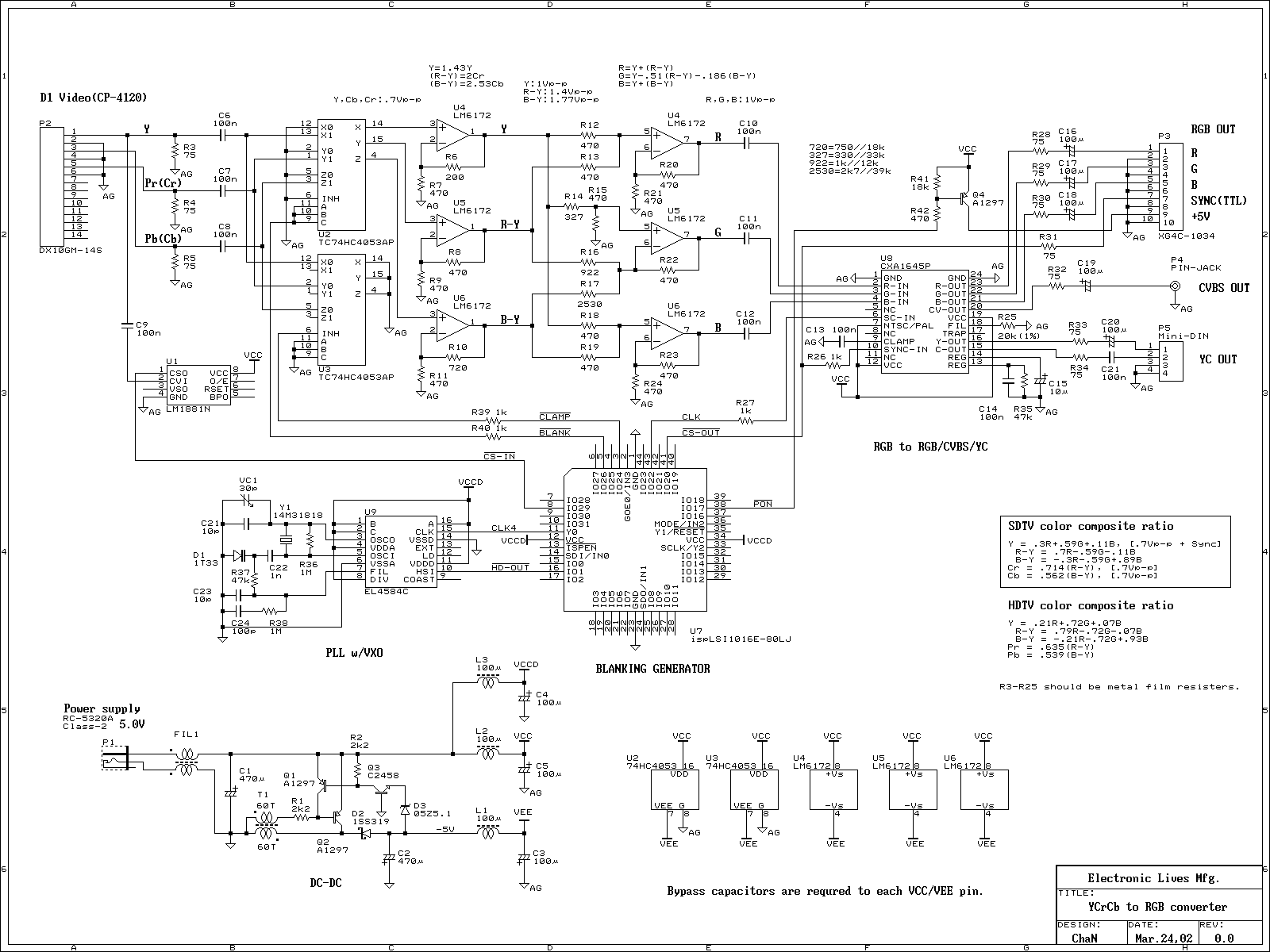
YUV/YCbCr to RGB converter
The device functions as a video recorder, DVD player, and TV game console, featuring a component video output. The component video signal resembles an RGB video signal; however, it is incompatible with RGB monitors.
The device's component video output is designed...

Small or Mini Audio Amplifier Circuit using TDA 7052 IC-Deliver 2 Watts
A compact audio amplifier circuit utilizing the TDA 7052 integrated circuit from Philips. This circuit is suitable for use as a pocket radio amplifier, delivering an output power of 2 watts.
The TDA 7052 is a low-voltage audio amplifier designed specifically...
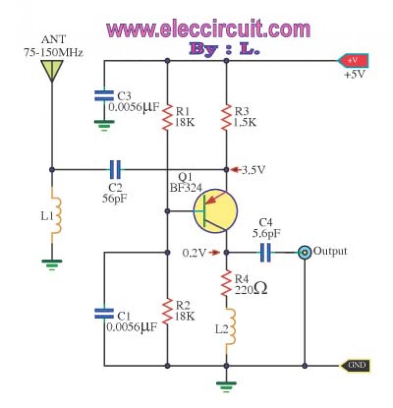
Wide band high frequency amplifier circuit
This is a wideband high-frequency amplifier circuit designed for a frequency range between 75-150 MHz. It utilizes a PNP transistor amplifier to enhance signal strength before it reaches the receiver of devices such as phones, FM radios, or amateur radios....
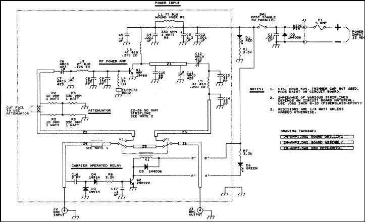
The FARA 2 meter amplifier project
This article discusses a 2-meter amplifier capable of delivering an output of 25-30 watts. Over 35 units have been acquired at a cost of less than $50 each in bulk. Photo A displays the final version of the circuit board,...