

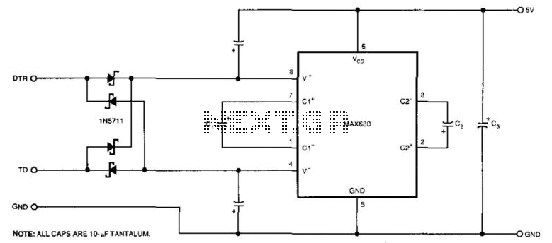

Rs-232C Line-Driven Cmos Circuits
The circuit illustrates a way to power CMOS ICs from RS-232C lines. The MAX680 is normally used to genera...
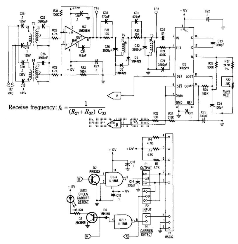
Carrier-Current Receiver For Data Transmission
This receiver consists of an input network amplifier IC7 FSK PLL detector ICG, and output am...
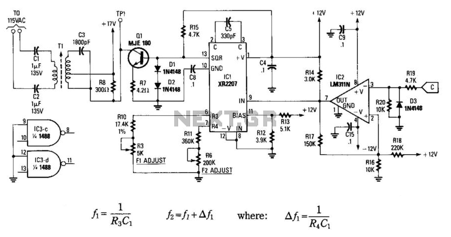
Carrier Current Transmitter For Data Transmission
In this circuit, data at input C is amplified by IC2 and then fed to modulator IC1. IC1 g...
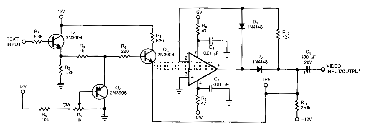
Composite-video-signal-text-adder
This circuit shows a simple way to add text information to a composite-video signal that might be floating at some indeterminate de level. The text generator a...

Rgb-composite-converter
The incoming RGB inputs are terminated with resistors Rl, R2, and R3 and potentiometers RVl, RV2, and RV3. These provide input impedances of approximately 75 0...
Low-cost-half-duplex-information-transmission-link
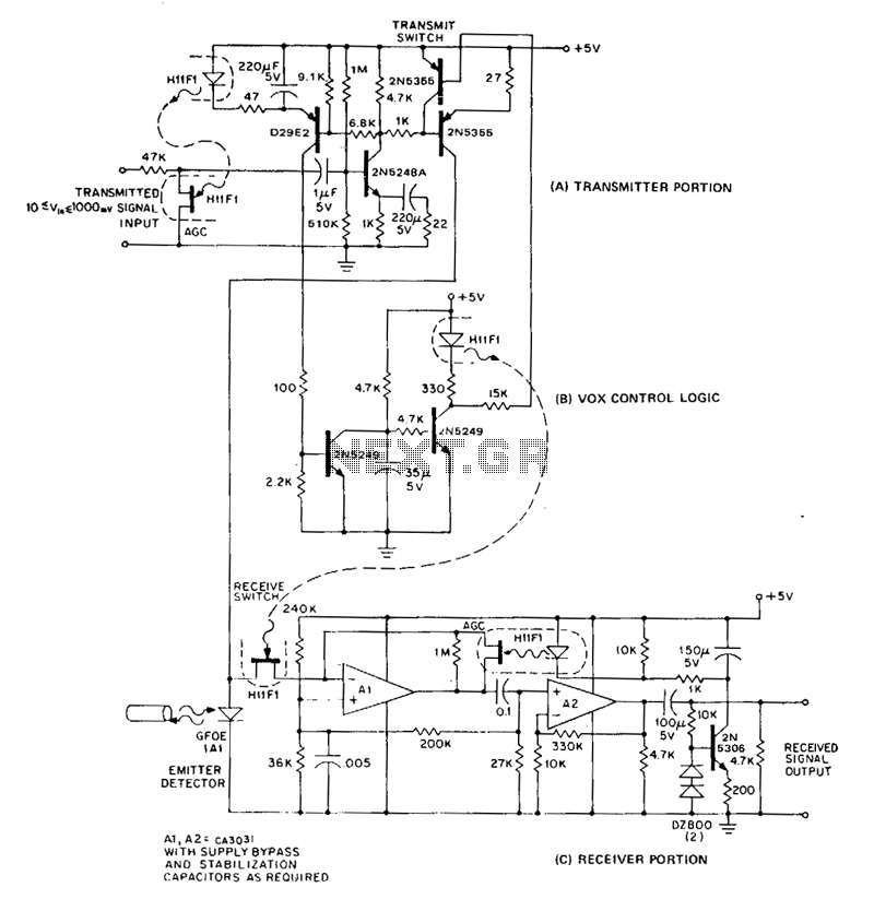
In a half-duplex system, information can flow in both directions, but only one direction at any given time. The conventional method of building a half-duplex l...
Digital-data-line-receiver
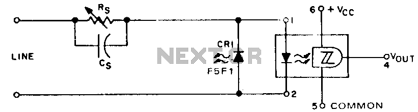
When digital data is transmitted over long lines (longer than 1 meter), proper transfer is often disturbed by the parasitic effects of ground level shifts and ...
Optical-ttl-coupler
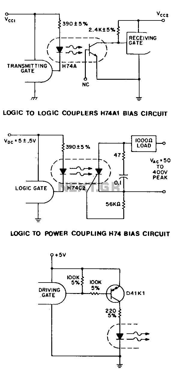
For higher speed applications, up to 1-MHz NRZ, the Schmitt-trigger output HllL series optoisolator provides many features. The 1.6-mA drive current allows fan-...
Optical-cmos-coupler
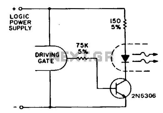
Since standard CMOS logic operates down to 3-V supply voltages and is specified as low as 30 p.A maximum current sinking/sourcing capability, it is necessary...
10F8-channel-transmission-system
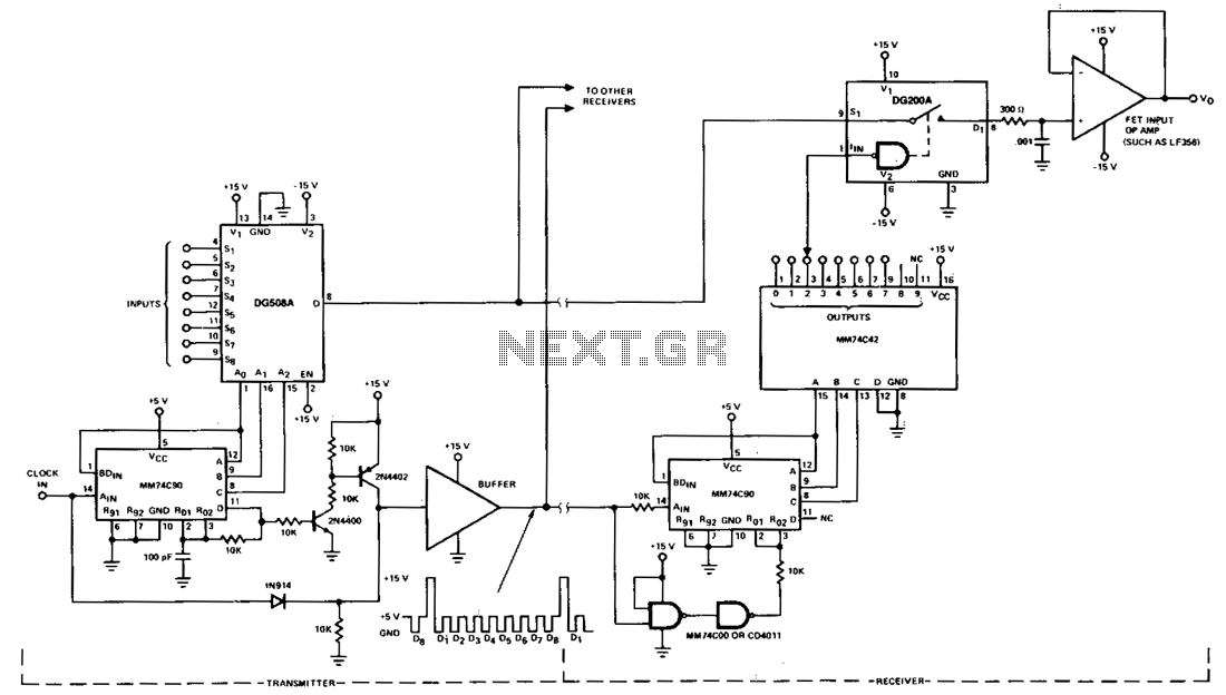
This circuit shows a typical multiplex system intended to carry one of 8 inputs into a remote location. A 5-V pulse train is sent down a separate channel to pe...
10F15-cascaded-video-mux
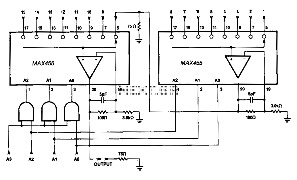
Two MAX455s can be cascaded to form a 1 of 15 video MUX by connecting the output of one MUX to one of the input channels of a second MUX. ...
Ir-receiver
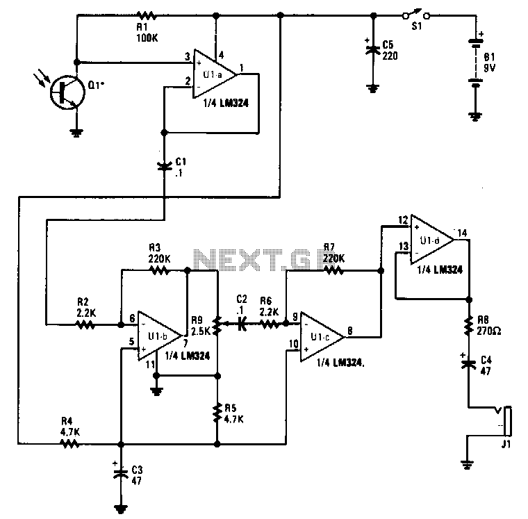
Infrared emissions detected by Ql are fed through Ula to Ulb, which amplifies the signal by a factor of 100. The amplified output ofUlb is fed to Ulc through R...
Fiber-optic-receiver
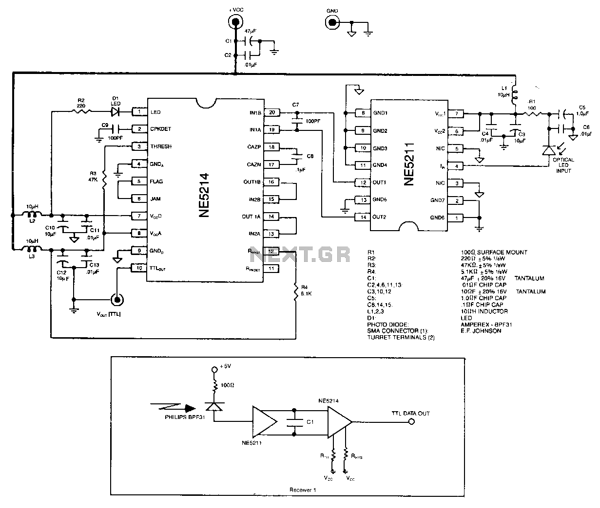
The optical signal is coupled to the pin diode. Current flowing in the diode also flows into the input of the NE5211 preamplifier. The preamplifier is a fixed-...
100M-baud-fiber-optic-receiver
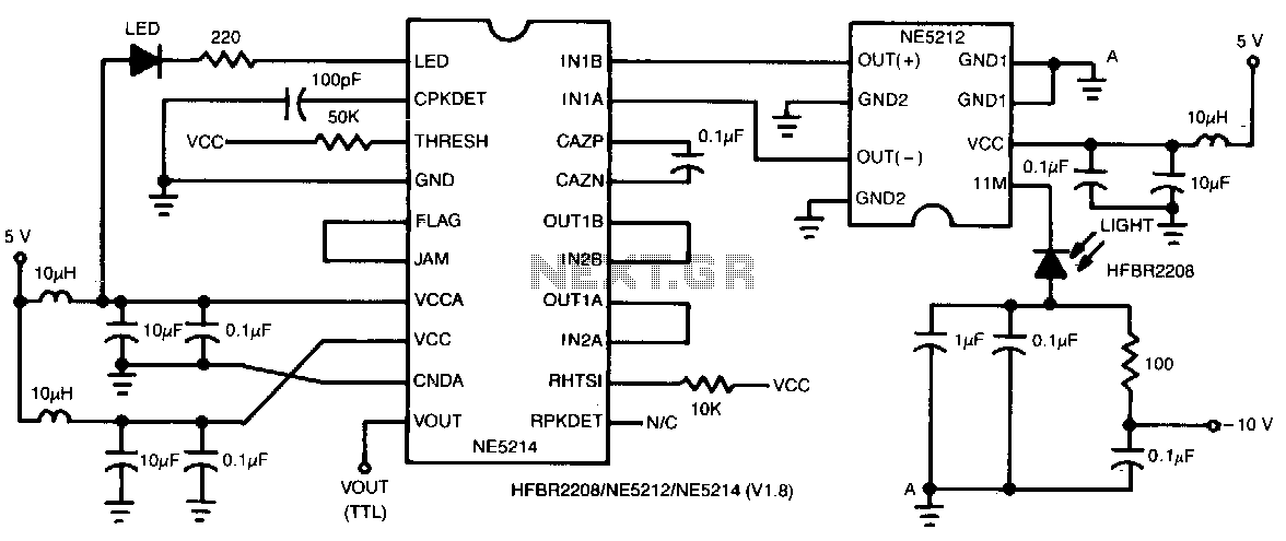
This two-chip receiver with minimum external component count has been designed for low-cost fiber optic applications to 100-M baud (50 MHz). The receiver is di...
Fiber-optic-link
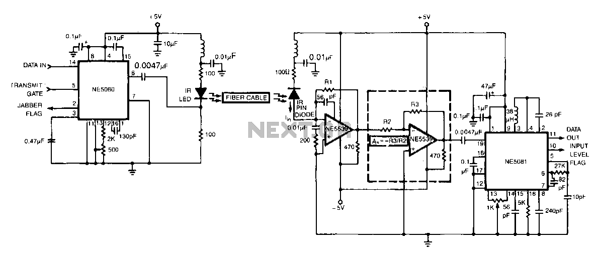
The circuit shows a simplex fiber link between the NE5080 transmitter and the NE5081 receiver. The components shown are for a center frequency of 5 MHz, althou...
Digital-fiber-optic-receiver
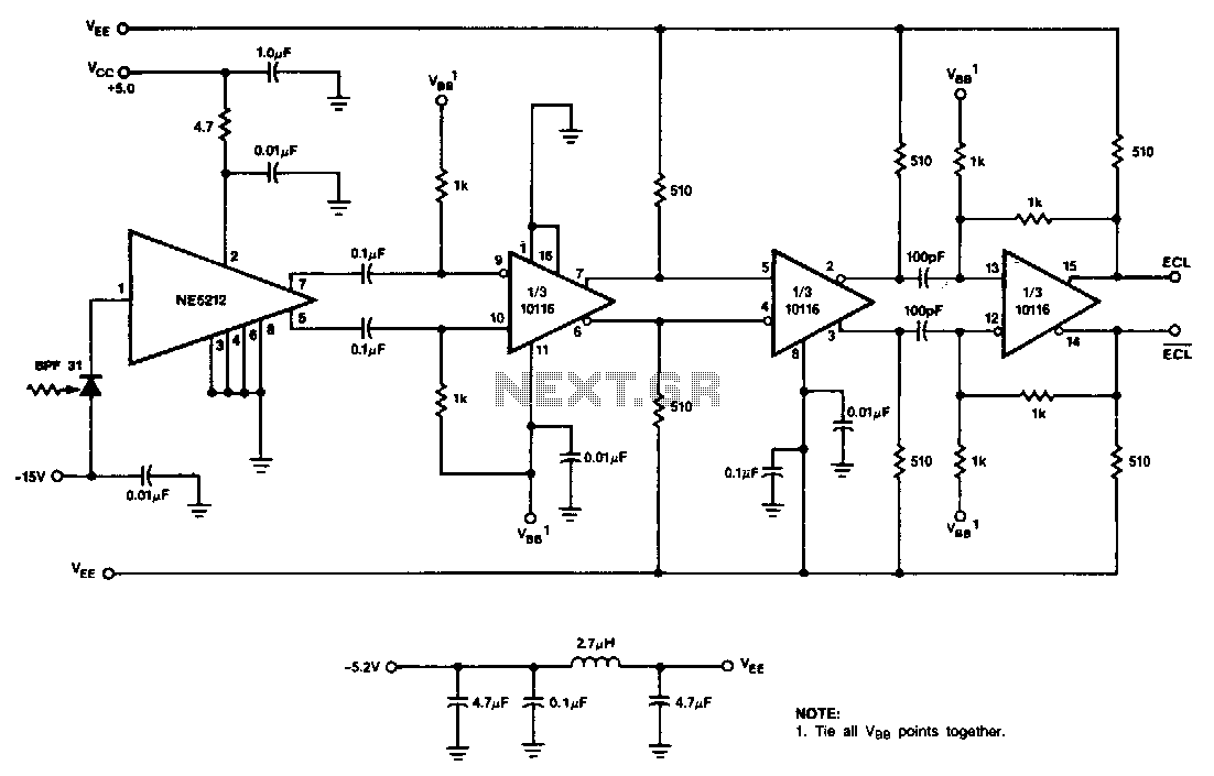
This receiver uses the NE5212, the Signetics 10116 ECL line receiver, and the Phillips/Amperex BPF31 pin diode. The circuit is a capacitor-coupled receiver and...
Fiber-optic-transmitter
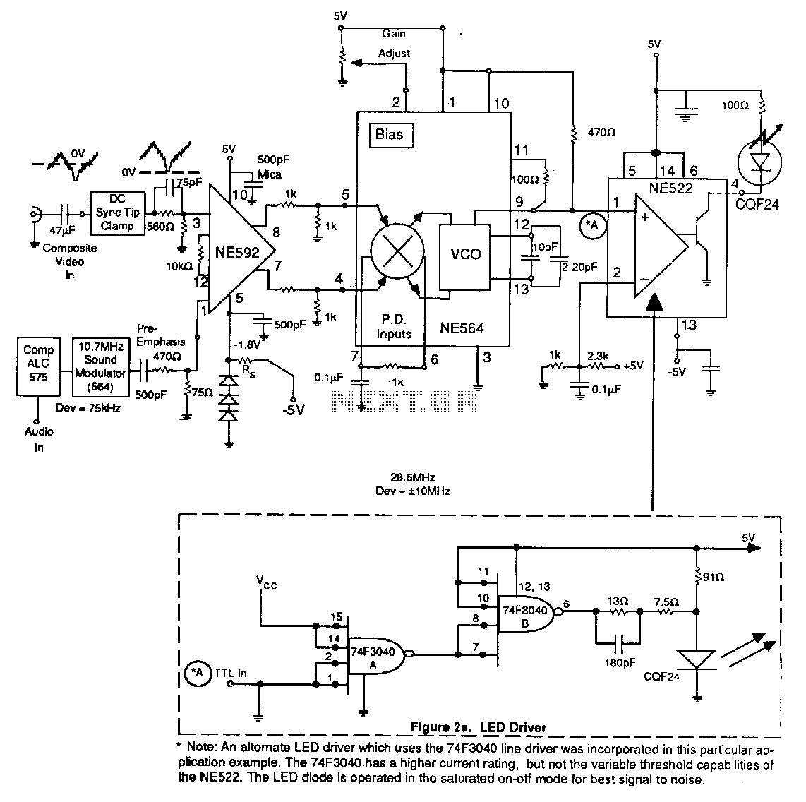
An alternate LED driver which uses the 74F3040 line driver was incorporated in this particular application example. The 74F3040.has a higher current rating, bu...
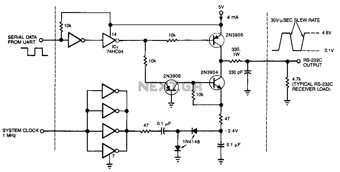
Low-power-rs-232c-driver
This circuit draws only 4 mA from a 5-V supply while driving a standard RS-232C receiver. The system clock drives a de-de converter that produces -3.4 V. The f...
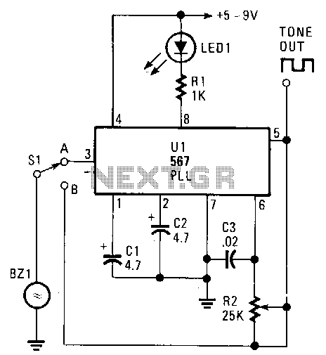
Encoder-decoder
The transducer circuit can be operated as either a tone encoder or decoder by changing the position of Sl. The operating frequency of that dual-purpose circu...
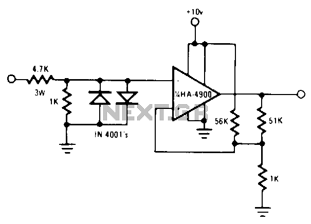
Rs232c-led-circuit
Use a pair of Maxim"s 5V-powered MAX231 RS-232C transmitters as drivers to obtain a 2-color LED. The transmitters require only a singleended, 5-V input to gener...