
digital room thermometer using lm35 sensor 8051 microcontroller
The interfacing of an LCD with the 8051 microcontroller AT89S52 requires careful consideration of the connections and programming to ensure proper functionality. The LCD module typically utilizes a parallel interface, where data lines (DB0 to DB7) and control lines (RS, RW, E) must be correctly connected to the microcontroller. In this case, it appears that the LCD is not receiving the expected signals, resulting in the display of black boxes, which indicates that the LCD is powered but not initialized or receiving data correctly.
To troubleshoot the issue, several steps should be taken. First, verify the wiring against the schematic to ensure that all connections are correct, particularly the data and control pins. For the AT89S52, the data lines can be connected to port 3, and the control lines should be connected to designated pins as per the LCD datasheet. Ensure that the power supply to the LCD is stable at the required voltage (typically +5V) and that the ground connections are secure.
Next, review the initialization code for the LCD. The initialization sequence typically involves sending a series of commands to set the display mode, cursor position, and other parameters. Ensure that the timing between commands is adequate, as the LCD requires specific delays to process each command. In the C code, the proper sequence of commands must be followed, including setting the function set, display control, and entry mode set.
It may also be beneficial to include diagnostic outputs in the C code to confirm whether the microcontroller is sending the correct signals to the LCD. This can be done by toggling an LED or using a multimeter to check the voltage levels on the data lines during the initialization process.
For the ADC0808 interfacing, ensure that the connections are made properly, and that the reference voltage is set correctly to correspond with the expected input from the LM35 temperature sensor. The ADC's output can be read through the microcontroller's port 3, and the corresponding C code should handle the conversion and display of the ADC results on the LCD.
If inconsistencies in output voltage from the microcontroller pins are observed, check for potential short circuits, incorrect resistor values, or faulty components. It is crucial to ensure that the microcontroller is functioning correctly and that the programming environment is set up to simulate the circuit accurately in Proteus.
In summary, careful examination of the circuit connections, thorough testing of the C code, and systematic troubleshooting will be essential to resolve the issues with the LCD and ADC interfacing with the AT89S52 microcontroller.Interface the LCD with 8051 microcontroller at89s52. But whenever I power up the microcontroller, LCD is lit but only black boxes are showing. I have tried many different codes and many things, but display is same. onle black boxes. But i have simulated this circuit in proteus. here, that LCD is giving correct output. Plz help in determining the problem. Here are the attached code and circuit diagram. Here is the C Code. Thanx. Now the c code is compiled successfully. But I cant run this program in Proteus simulator. It dows not give any output. I can not find pin 6 of that LCD module. So i have to change circuit a bit. Plz modify it if necessary. . . I have used lm032l and this time result is positive. though a small error much like warning is displayed in proteus. I am attaching modified. /files with code. Sir, as today our burner didnt work, so we cant test that circuit. will test again tomorrow. mean while I need help also for completing our main project : digital room thermometer as our mentor are out of touch of these microcontroller and these things and it is too much to handle of our own. So, plz help. I am attaching circuit diagram here. At first, tell me the important things to test in order to start that project finally. We have tested 2) tested ADC 0808 in free running mode and it is giving correct output. We kept reference voltage 1. 28 volt so that the step size is in accordance with lm35 step size. next thing to test is ADC with microcontroller. coz You will test your LCD so there will be a display to print your test results. You guys are going on the right track give us some ideas for how to test adc with microcontroller what things we have to include in the c code then i can write it now and post here to verify.
will u plz rep. sooner we have a deadline ahead sooner, so we have to grasp the concept and as well as programming. so, plz help Thanx. very thorough tutorial. Now using that 8051 code, the output will be at microprocessor port 3. . so, how can we read microprocessor output from port 3 do we have to use LCD alongwith microprocessor( connect LCD dataport to p3 of microprocessor) and adc to make it work or only microprocessor and adc can be used its only an example. You need to modify it as per your need. It would be great to get LCD working first coz you can use it later when testing adc and sensor with controller.
Got your point. I am going to try to simulate LCD, microcontroller and ADC in proteus and accordingly modify the code. after some time, i will post the code and proteus schematic for your reference. And if that works too, we can test LCD and then adc interfacing microcontroller too tomorrow. . Posting it after sometime and Thanx a problem while simulating, the led outputs are low at almost 0 v, that`s ok but high at 2.
5 volt. I think their high voltage should be 5v. any idea why this is happening really disheartened. . we have been trying to initialise that LCD for several times ( for past couple of days). today we did everything just like in circuit and did everything in order. yet only black boxes are shown. Few things have been noted down. 1) when we connect only pin 15, 16 and 1, 2, 3 properly as in ckt diagram, then also black boxes are showing. THESE BOXES ARE IN 2nd ROW. . that means microcontroller can`t send any data to that LCD. 2) We have been checking output from every pin of microcontroller. According to proteus, we should be getting high value for db0, db6 and db7 in LCD and other pin should be low.
But, today we got either all 0 or all 5 volt. Strange thing, output voltage of microcontroller pins are sometimes 1. 5 volt, sometimes 5 volt and sometimes 0. What can be possibly wrong can you post your circuit and schematic And keep in mind that you cannot drive LEDs directly from micrcontroller. controller pins unless you`re connecting LEDs in -ve logic. 🔗 External reference
Related Circuits

In August 2007, an individual with a passion for photography acquired a Panasonic FZ30 digital camera and joined a forum on dpreview dedicated to Panasonic products. A fellow forum member, who was a programmer and electronics enthusiast, created a...
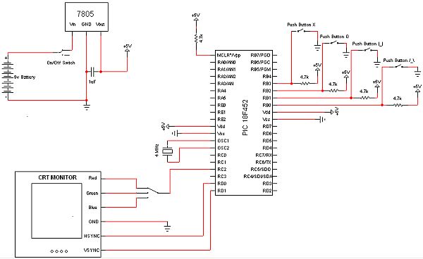
The objective of this project is to develop a device capable of outputting VGA signals to a CRT monitor to display figures, text, and characters. The project involves designing a circuit that generates standard VGA signals, which include separate horizontal...
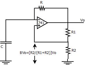
The positive feedback comparator circuit enhances the gain of the operational amplifier (op-amp), facilitating rapid switching between the two states of a multivibrator. This positive feedback also introduces hysteresis into the circuit. A capacitor, denoted as `C`, is connected...

Numerous LED projects to ignite creativity. Light Emitting Diodes are easy to use and enhance the appearance of DIY electronic projects. LEDs (Light Emitting Diodes) are semiconductor devices that emit light when an electric current passes through them. They are...
This is a Class D audio amplifier circuit that is used to control PWM motor speed. This circuit has two advantages for battery-powered portable devices. First, The Class D audio amplifier circuit is designed to efficiently manage the speed...
The Atmel Flash devices are ideal for developing, since they can be reprogrammed easy and fast. If you need more code space for your application, particularly for developing 89Cxx projects with C language. Atmel offers a broad range of...