


Control your Holiday Lights with a Magic Wand
#holiday lights
#magic wand
#magnet
#sequence control
#lighting control
#automation
#DIY
#decorative lighting
#wireless control
#sensor
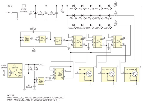
Description: This circuit enables the activation of holiday bulbs with a wave of a magic wand. The strings of lights flash in a sequential manner. The core concept relies on a magnet.
The circuit operates by utilizing a magnet as the primary triggering mechanism. When the magic wand, which is equipped with a magnet, is waved near the circuit, it induces a response in the electronic components. The main components of the circuit include a microcontroller, which processes the input signal from the magnet, and a driver circuit that controls the power to the holiday bulbs.
The microcontroller is programmed to recognize the presence of the magnetic field and activate the output in a predetermined sequence. This sequence can be customized to create various lighting effects, enhancing the festive atmosphere. The driver circuit typically consists of transistors or relays that can handle the current required to power the bulbs without exceeding their ratings.
Additionally, the circuit may incorporate a power supply unit to ensure stable voltage and current levels for reliable operation. Safety features, such as fuses or circuit breakers, can be included to protect against overloads. The overall design emphasizes simplicity and user-friendliness, making it an ideal project for hobbyists and those looking to add a touch of magic to their holiday decorations.This circuit allows you to turn on your holiday bulbs with a wave of the magic wand. The strings flash in sequence. At the heart of the idea is the magnet..
The circuit operates by utilizing a magnet as the primary triggering mechanism. When the magic wand, which is equipped with a magnet, is waved near the circuit, it induces a response in the electronic components. The main components of the circuit include a microcontroller, which processes the input signal from the magnet, and a driver circuit that controls the power to the holiday bulbs.
The microcontroller is programmed to recognize the presence of the magnetic field and activate the output in a predetermined sequence. This sequence can be customized to create various lighting effects, enhancing the festive atmosphere. The driver circuit typically consists of transistors or relays that can handle the current required to power the bulbs without exceeding their ratings.
Additionally, the circuit may incorporate a power supply unit to ensure stable voltage and current levels for reliable operation. Safety features, such as fuses or circuit breakers, can be included to protect against overloads. The overall design emphasizes simplicity and user-friendliness, making it an ideal project for hobbyists and those looking to add a touch of magic to their holiday decorations.This circuit allows you to turn on your holiday bulbs with a wave of the magic wand. The strings flash in sequence. At the heart of the idea is the magnet..
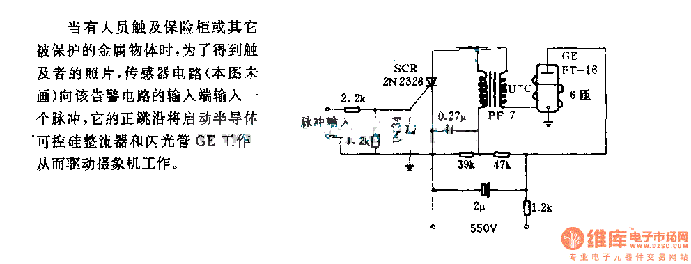
The alarm circuit diagram for safety box and other metal objects
When an individual touches the safety box or other protected metal objects, the sensor circuit generates a pulse to the alarm circuit. The positive edge of this pulse activates the semiconductor and thyristor flash GE, subsequently triggering the camera to...

SR63 holiday lights ASIC
220V AC is converted to DC after passing through a VDI ~ VD4 bridge rectifier. The output from one point supplies power directly to lights H1 through H4. Another route passes through R1, a buck converter, and VD5, which regulates...
SR63 holiday lights ASIC
220V AC is converted to DC after passing through a VDI ~ VD4 bridge rectifier. The output from one point supplies power directly to lights H1 through H4. Another route passes through R1, a buck converter, and VD5, which regulates...
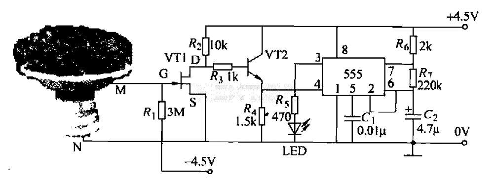
Pots water alarm circuit
The flowers in pots require watering, as relying solely on the observation of moist soil surfaces can be unreliable. To address this issue, a flower watering indicator has been developed. This circuit includes a field effect transistor (VT1), a second...

Crescendo ampilifier elektor1982
The Elector Crescendo was the first DIY amplifier that was not a kit. The design was sourced from the Elector magazines available at a local library.
The Elector Crescendo is an innovative audio amplifier designed for DIY enthusiasts. It features a...

Objects in Flux
The Open Source Automation project is a free automation software that operates on Windows and does not require programming for setup. It features a user-friendly graphical interface and includes unique functionalities that are not typically found in high-end security and...

lights 5GM168 control circuit diagram
Family karaoke lighting design incorporates various methods for circuit control. The control circuit described here features a four-way light output with loop jumping and speed control capabilities. A microphone detects the acoustic signal strength, allowing the lights to jump faster...
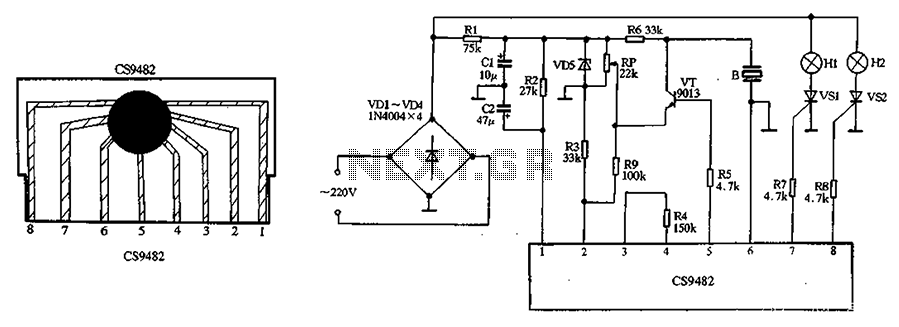
CS9482 holiday lights ASIC
The CS9482 integrated circuit fabrication is demonstrated with a holiday lights circuit. The CS9482 chip includes a 4.1V voltage regulator circuit; therefore, while the external circuit does not need to be regulated, if the voltage exceeds 4V, a current-limiting resistor...
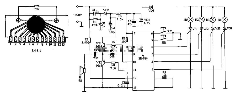
SH-816 ASIC holiday lights
The chip includes four built-in procedures for controlling double bond jumps, offering eight different jump patterns. Function selection is managed through button SB2, while button SB1 allows for additional features. The system can produce eight types of light-hop patterns, with...