


SH-80051 holiday lights ASIC
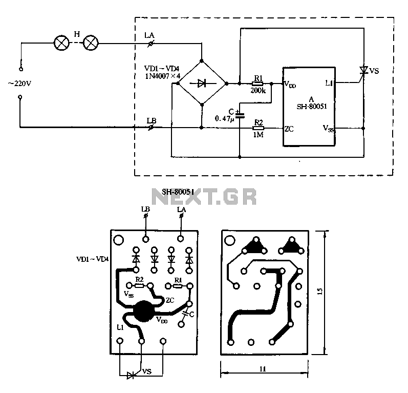
Description: Figure 2-85 illustrates a single-channel SH-80051 flash controller. The SH-80051 chip features four terminals: the positive power supply terminal (VDD), the synchronization input (zc), the negative power supply terminal (VSS), and the drive output (L1). The chip operates with 220V AC light strings connected to terminals L and LB. After being limited by resistor R1, the AC input is rectified by diodes VD1-VD4. Capacitors at the VDD and VSS terminals filter the power supply to the chip. Resistor R2 provides an AC synchronous signal to the chip. The output trigger pulse from terminal L1 adjusts the conduction angle of the SCR, enabling the string lights to flash. The SH-80051 supports six flashing patterns that automatically cycle through: 1) Flash A, 2) Flash B, 3) Slow Fade A, 4) Star Blink A, 5) Slow Fade B, and 6) Star Twinkle B.
The SH-80051 flash controller is designed for decorative lighting applications, particularly for use in holiday lights and similar products. The circuit's primary function is to control the flashing of light strings by regulating the conduction angle of a silicon-controlled rectifier (SCR), which allows for precise control of the light output.
The power supply section of the circuit includes a 220V AC input, which is connected to the L and LB terminals of the chip. Resistor R1 serves as a current-limiting component, ensuring that the voltage and current levels are appropriate for the subsequent rectification stage. The rectification is performed by diodes VD1 to VD4, which convert the AC voltage to a pulsating DC voltage suitable for the chip's operation.
The VDD and VSS terminals are connected to a filtering capacitor, which smooths out any voltage fluctuations, providing a stable power supply to the chip. This stability is crucial for the reliable operation of the flashing patterns. Resistor R2 is used to generate an AC synchronous signal that is essential for timing the flash sequences.
The output from terminal L1 triggers the SCR, which is responsible for turning the light strings on and off. By adjusting the conduction angle of the SCR, the brightness and flashing frequency of the lights can be varied. This feature allows for various visual effects, making the lighting more dynamic and appealing.
The SH-80051 chip is programmed with six distinct flashing patterns, which can be selected and cycled through automatically. Each pattern offers a unique lighting effect, enhancing the aesthetic appeal of the light display. The patterns include rapid flashing, slow fading, and twinkling effects, which can be used to create different moods and atmospheres.
Overall, the SH-80051 circuit is a versatile and effective solution for controlling decorative lighting, providing users with a range of customizable options for their lighting displays.Figure 2-85 is a single road SH-80051 produced flash string, SH-80051 chip only four ports: positive power supply terminal VDD; synchronization input zc; negative power supply terminal vss; drive output Ll. 220V AC by light strings H input to terminal L and LB, by the well-limiting by Rl down after VDI-VD4 rectification, VDD and vss end C filter was added to the chip, R2 provides AC synchronous signal chip, Lt on output trigger pulse to change change vs SCR conduction angle, so as to achieve the purpose of string lights flashing H. SH-80051 There are six blinking patterns function, can automatically flip cycle. Six kinds of patterns specifically: 1, flashes A: 2, flashes B; 3, slowly fades A; 4, the stars blinking A; 5, slowly fades B; 6, stars twinkling B.
The SH-80051 flash controller is designed for decorative lighting applications, particularly for use in holiday lights and similar products. The circuit's primary function is to control the flashing of light strings by regulating the conduction angle of a silicon-controlled rectifier (SCR), which allows for precise control of the light output.
The power supply section of the circuit includes a 220V AC input, which is connected to the L and LB terminals of the chip. Resistor R1 serves as a current-limiting component, ensuring that the voltage and current levels are appropriate for the subsequent rectification stage. The rectification is performed by diodes VD1 to VD4, which convert the AC voltage to a pulsating DC voltage suitable for the chip's operation.
The VDD and VSS terminals are connected to a filtering capacitor, which smooths out any voltage fluctuations, providing a stable power supply to the chip. This stability is crucial for the reliable operation of the flashing patterns. Resistor R2 is used to generate an AC synchronous signal that is essential for timing the flash sequences.
The output from terminal L1 triggers the SCR, which is responsible for turning the light strings on and off. By adjusting the conduction angle of the SCR, the brightness and flashing frequency of the lights can be varied. This feature allows for various visual effects, making the lighting more dynamic and appealing.
The SH-80051 chip is programmed with six distinct flashing patterns, which can be selected and cycled through automatically. Each pattern offers a unique lighting effect, enhancing the aesthetic appeal of the light display. The patterns include rapid flashing, slow fading, and twinkling effects, which can be used to create different moods and atmospheres.
Overall, the SH-80051 circuit is a versatile and effective solution for controlling decorative lighting, providing users with a range of customizable options for their lighting displays.Figure 2-85 is a single road SH-80051 produced flash string, SH-80051 chip only four ports: positive power supply terminal VDD; synchronization input zc; negative power supply terminal vss; drive output Ll. 220V AC by light strings H input to terminal L and LB, by the well-limiting by Rl down after VDI-VD4 rectification, VDD and vss end C filter was added to the chip, R2 provides AC synchronous signal chip, Lt on output trigger pulse to change change vs SCR conduction angle, so as to achieve the purpose of string lights flashing H. SH-80051 There are six blinking patterns function, can automatically flip cycle. Six kinds of patterns specifically: 1, flashes A: 2, flashes B; 3, slowly fades A; 4, the stars blinking A; 5, slowly fades B; 6, stars twinkling B.
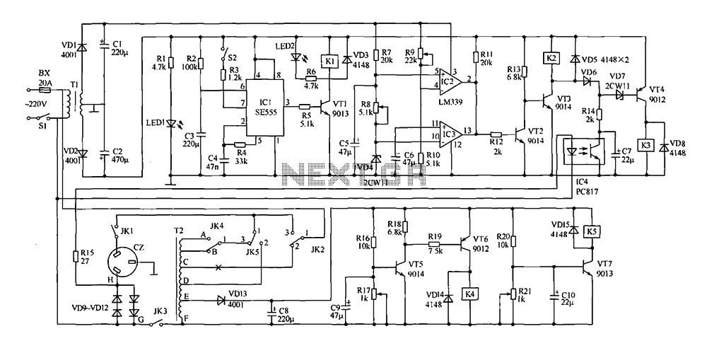
Saving voltage regulator circuit
This document presents a power-saving voltage regulator circuit. In addition to its general function as a delay regulator, the circuit features: (1) an automatic voltage regulation capability for mains voltage within a range of 220V ±10%, allowing direct power supply...
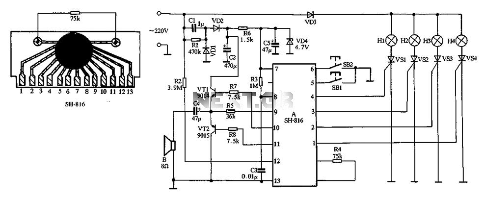
SH-816 ASIC holiday lights
The chip includes four built-in procedures for controlling double bond jumps, offering eight different jump patterns. Function selection is managed through button SB2, while button SB1 allows for additional features. The system can produce eight types of light-hop patterns, with...
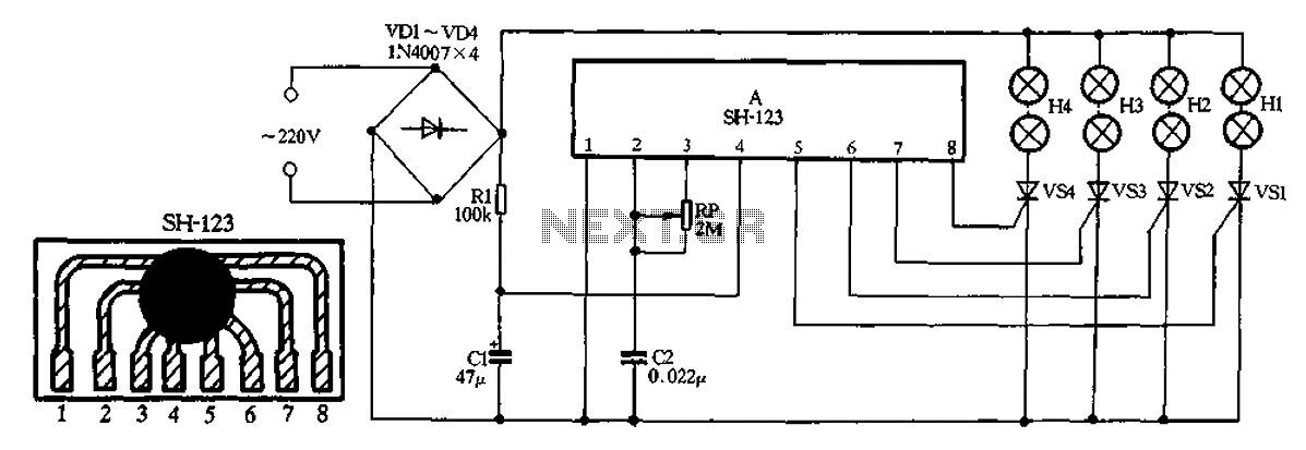
SH-123 ASIC holiday lights
A 220V AC input is processed by a bridge rectifier consisting of diodes VD1 to VD4, which supplies electricity to four lights labeled H1 to H4. The circuit includes a limiting resistor R1 and a filter capacitor C1 to stabilize...
Circuit diagrams and Schematic
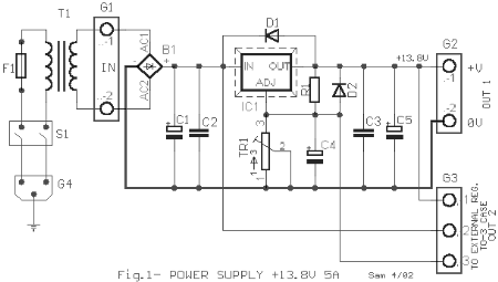
This AC to DC power supply can output 5A in continuous operation and 12A peak current. This type of DC power supply uses a PCB, allowing for two case types for IC1: TO-220 or TO-3. The regulation of this 12-volt...
FSP107-2PS01 two-in-one power panel circuit analysis
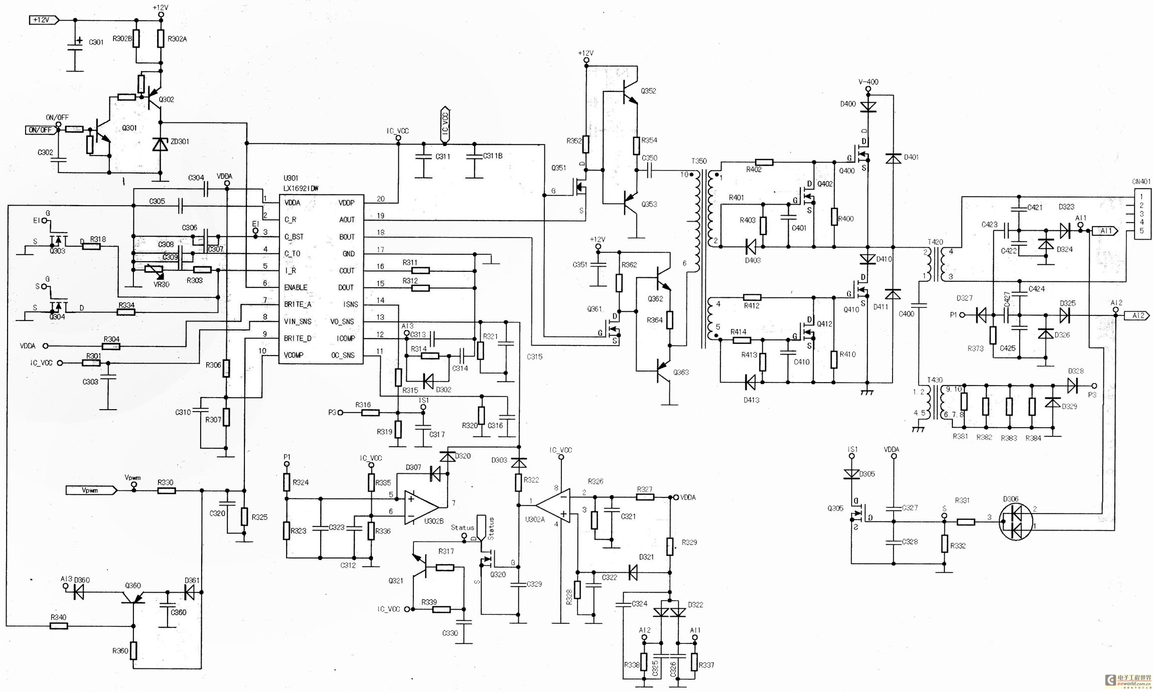
The main component is the LG26 one-inch screens integrated with the FSP107-2PS01 two-in-one electrical power package, which utilizes a direct drive CCFL modulator tube. This setup is compatible with screens from other manufacturers, such as Samsung and AU, but requires...
Batteries charger & PSU - ideal for digital camerass
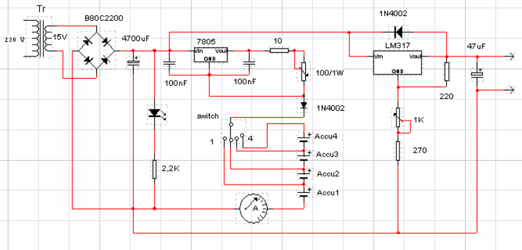
This circuit was designed for digital cameras, which are known to have significant power consumption. For instance, the Minolta E223 camera requires approximately 800 mA. In practice, this demand can be met using a mains power supply or high-capacity NiMH...
Switching power supply monolithic switching regulator DN-25 configuration
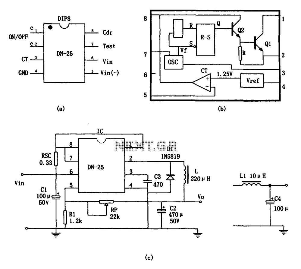
As shown in the figure, the DN-25 IC is a switching power supply. The DN-25 is a monolithic switching power supply device suitable for medium output current applications and a wide voltage range. Its main performance indicators include an input...
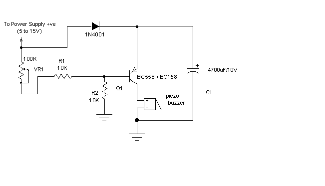
power supply alarm circuit
Most of the power supply failure indicator circuits need a separate power supply for themselves. But the alarm circuit presented here needs no additional supply source. It employs an electrolytic capacitor to store adequate charge, to feed power to the...
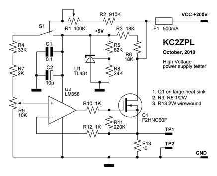
KC2ZPLs Web Design and Electronic Home
Now that these power supplies are available, it would be beneficial to evaluate their performance. Traditionally, an adjustable load (a robust resistor) is connected to the output to measure both output voltage and current at various points. This allows for...