

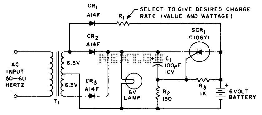

Single source emergency lighting system
This emergency lighting system maintains a 6 volt battery at full charge and switches...
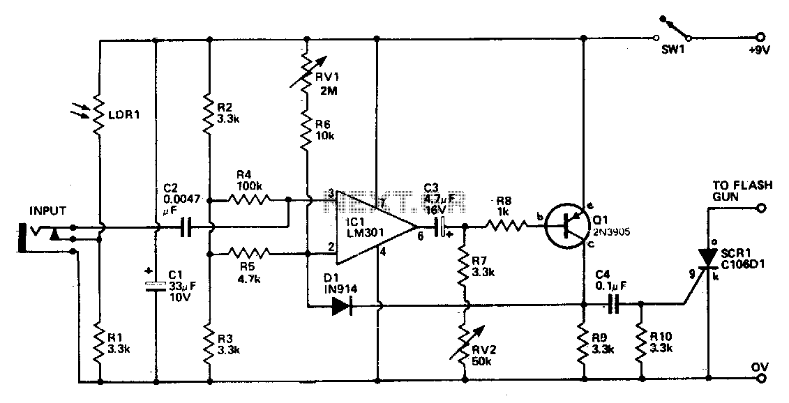
Sound light-flash trigger
Sound input to the microphone triggers the IC monostable circuit which subsequently triggers an SCR, and hence the flash, after a time delay...
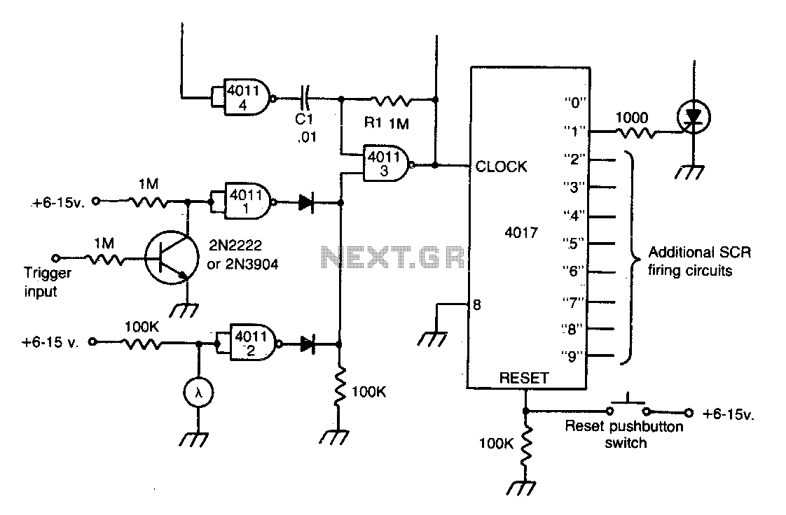
Photo stop action
This circuit gives multiple "stop-action" photographic effects like showing a bouncing ball in up to nine locations in a single photograph. The circuit will aut...
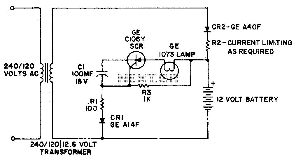
Emergency light
This simple circuit providers battery operated emergency lighting instantaneously upon failure of the regular ac service. When line power is restored, the emerg...
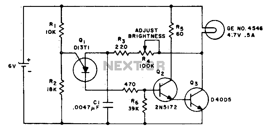
Low loss brightness control
This circuit changes the average value of the dc supply voltage because of the high switching frequency. The tungsten lamp will have an almost continuous adjust...
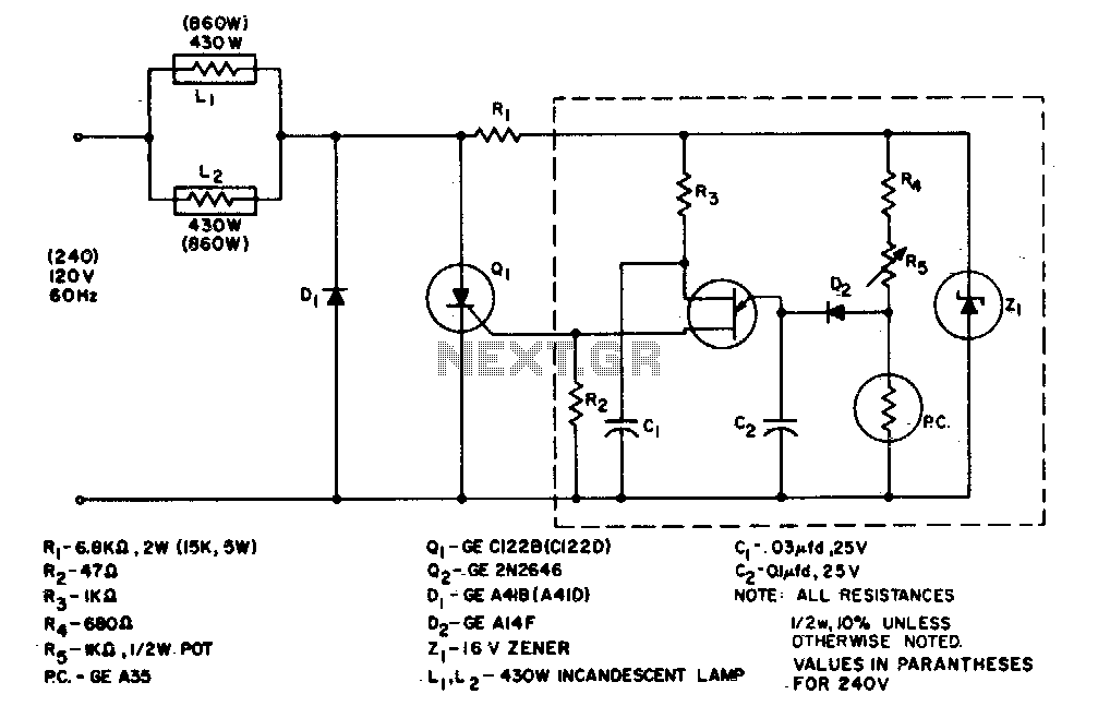
860 Watt limited-range light control
The system is designed to regulate an 860 watt lamp load from half to full power. This is achieved by the controlled-half-plus-fixed-half-wave phase control met...

Low cost lamp dimmer
Without a heats ink, Triac Ql handles up to a 400-watt lamp. The neon lamp does not trip the gate until it conducts so the lamp turns on a medium brilliance...

Hysteresis-free phase control circuit
This circuit is intended for lamp dimming and similar applications. It requires only one RC phase lag network...
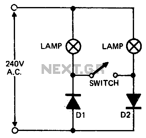
Floodlamp power control
When setting up photographic floodlamps, it is sometimes desirable to operate the lamps at lower power levels until actually ready to take the photograph. The c...
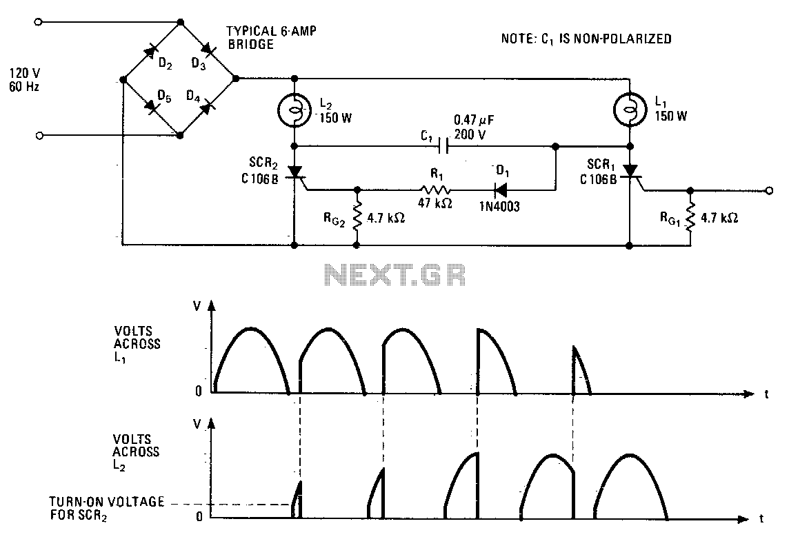
Complementary lighting control
This lighting-control unit will fade out one lamp while simultaneously increasing the light output of another. The two loads track each other accurately without...
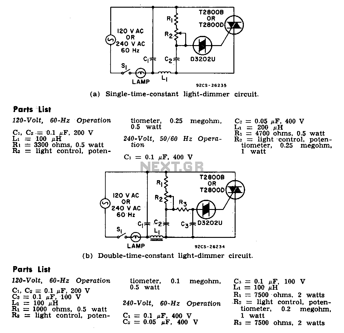
Light dimmers
The two lamp-dimmer circuits differ in that (a) employs a single-time-constant trigger network and (b) uses a double-time-constant trigger circuit that reduces ...
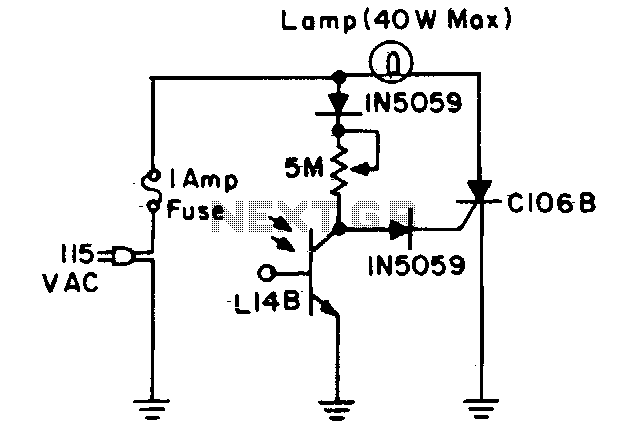
Automatic night light
During daylight hours, the L14B photo-Darlington QEDEC registered as 2N5777 through 2N5780) shunts all gate current to ground...
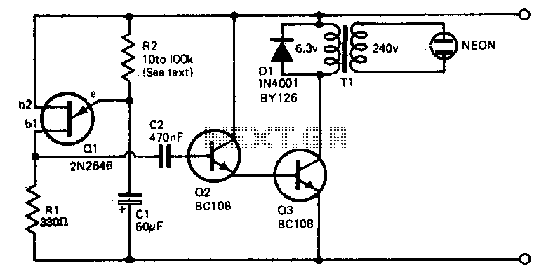
Neon tube flasher
The voltage required to ignite the neon tube is obtained by using an ordinary filament transformer (240-6 V) in reverse. Battery drain is quite low, around 1 to...
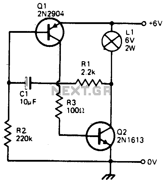
Transistorized flasher
This simple circuit will flash a 6 volt lamp at a rate determined by the size of capacitor CI. It is most economical on power as it only draws current when the ...
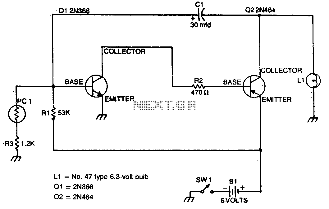
Automatic safety flasher
This flasher only comes on at night. It furnishes a bright nighttime illumination, and shuts itself off automatically as soon as the sun comes up...
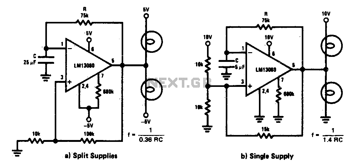
Low frequency lamp flasher-relay driver
This circuit is a low frequency warning device. The output of the oscillator is a square wave that is used to drive lamps or small relays...
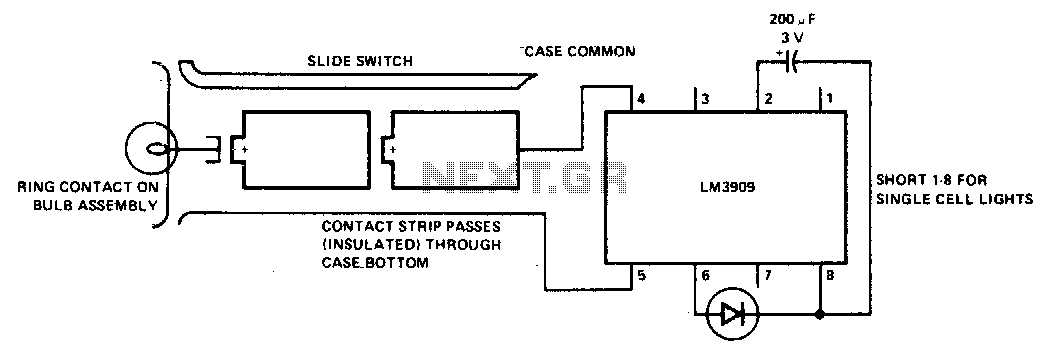
Flashlight finder
Notes: LM3909, Capacitor, and LED are Installed in a White Translucent Cap on the Flashlight"s Back End. Only One Contact Strip (in Addition to the Case Connect...
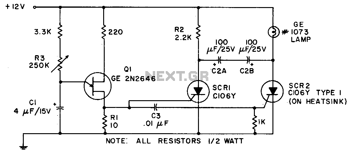
Auto boat or barricade flasher
Because of its ability to withstand the heavy inrush currents, this incandescent lamp flasher uses the C106 SCR...
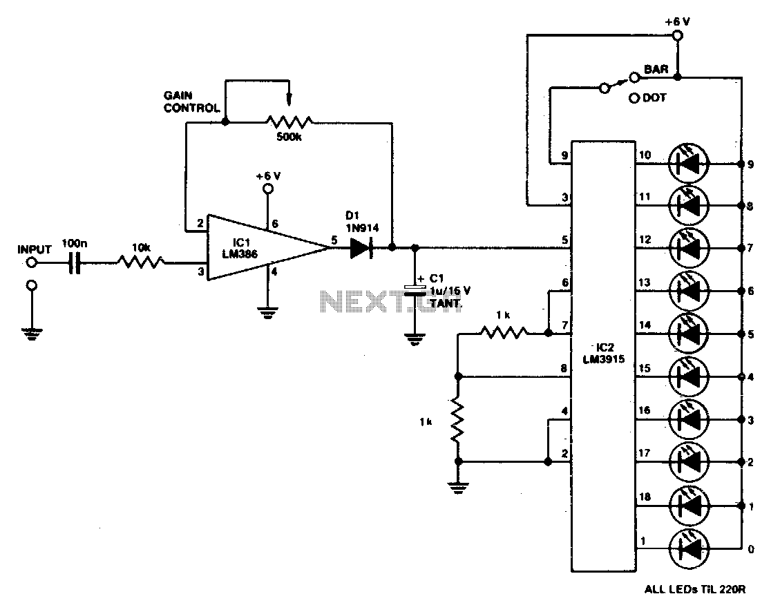
Led bar-dot level meter
A simple level of power meter can be arranged to give a bar or dot display for a hi-fi system. Use green LEDs for 0 to 7; yellow for 8 and red for 9 to indicate...

Led brightness control
The brightness of LED display is varied by using a photocell in place of one timing resistor in a 555 timer, and bypassing the other timing resistor to boost th...