

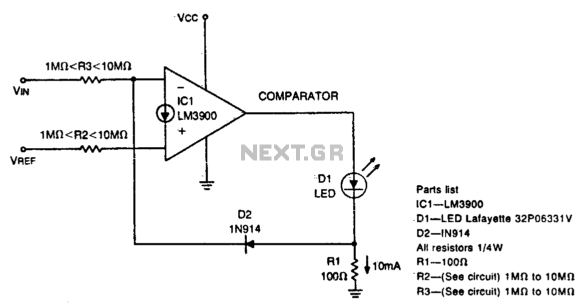

Diode feedback comparator
This circuit can drive anLED display with constant current independently of wide power supply voltage changes. It can operate with a power supply range of at le...
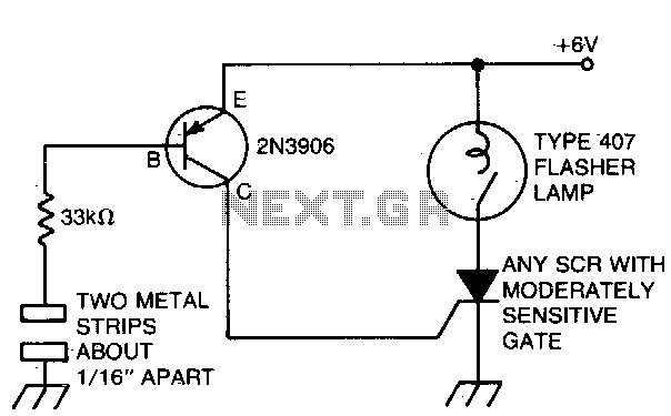
Capacitance switched light
The battery powered light turns on easily, stays on for just a few seconds, and then turns off again. The circuit is triggered when you place a finger across th...
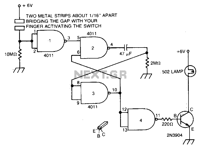
Capacitance operated battery powered light
Touch the plate and the light will go on and constant of the 47 µf capacitor and the 2M remain on...

Equipment on reminder
Due to the low duty cycle of flashing LED, the average current...
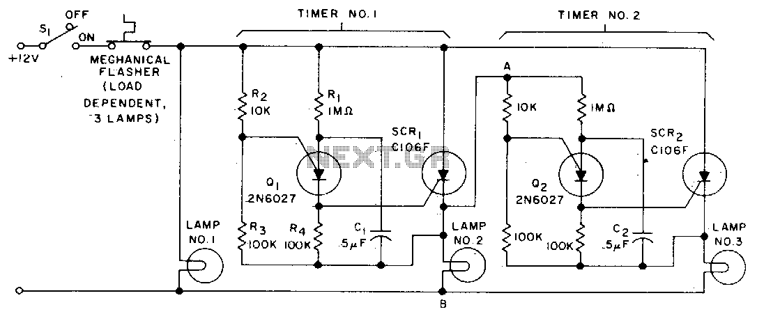
Sequential flasher
When the turn signal switch SI is closed, lamp #1 will be activated and capacitor Cl will charge to the triggered voltage of Ql. As soon as the anode voltage on...
LED tilt level
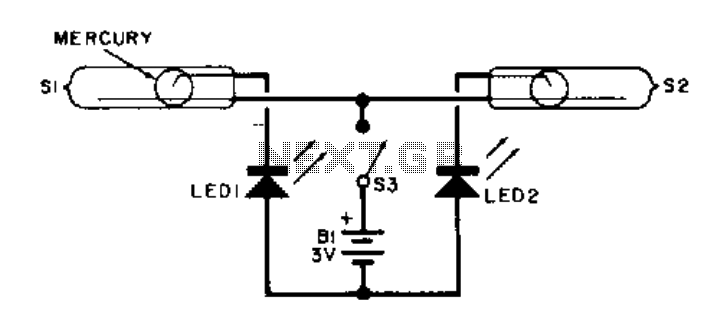
This electronic level uses two LED indicators instead of an air bubble. If the surface is tilted to the right, one LED lights; if it's tilted to the left, the o...
Phone light
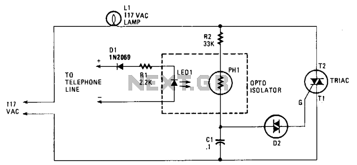
When the phone does ring the triac is triggered into conduction by a signal applied to its gate (G) through a bilateral switch (diac), D2....
Disco-strobe light
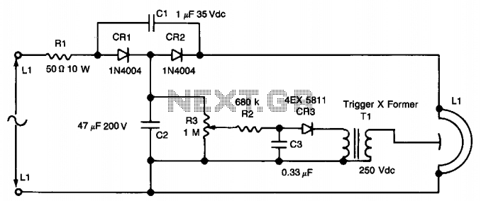
This circuit uses a voltage doubler CR1 and CR2 to obtain about 280 V dc across Cl. C2 and R3 form a voltage divider to obtain a dc voltage to change C3 thru R2...
Simple strobe circuit
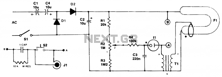
Initially the neon and xenon lamps are not conducting and act like a very high (almost infinite) resistance. Capacitors Cl and C4 in conjunction with DI and D2 ...
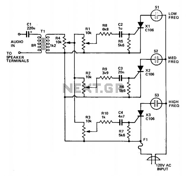
Color organ
Three lights are controlled by the three channels. One light will pulse in response to the bass, another illuminates with mid-range sounds, and the last lights ...
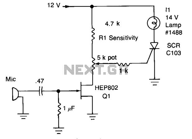
Sound-activated switch
Peaks of signal (adjusted by Rl) greater than about 0.7 volts trigger the SCR and light lamp II.
...
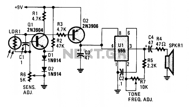
Sun wake-up call
A cadmium sulfide photocell (LDR1, which is a light-dependent resistor) is connected to the base and collector of an npn transistor, Ql. When light hits LDR1, t...
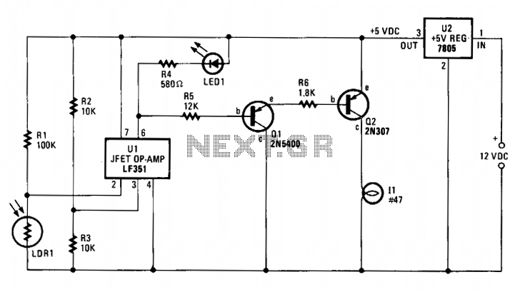
Automatic mooring light
Integrated-circuit Ul—an LF351 or 741 op amp—is used as a comparator to control the light. Resistors R2 and R3 provide a reference voltage of abou...
Warning light
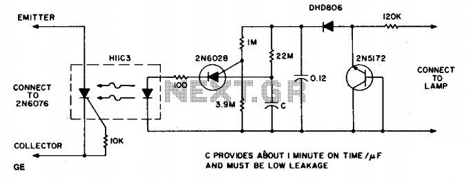
The circuit provides illumination when darkness comes. By using the gain available in darlington transistors, this circuit is simplified to use just a photodarl...
Tandem dimmer
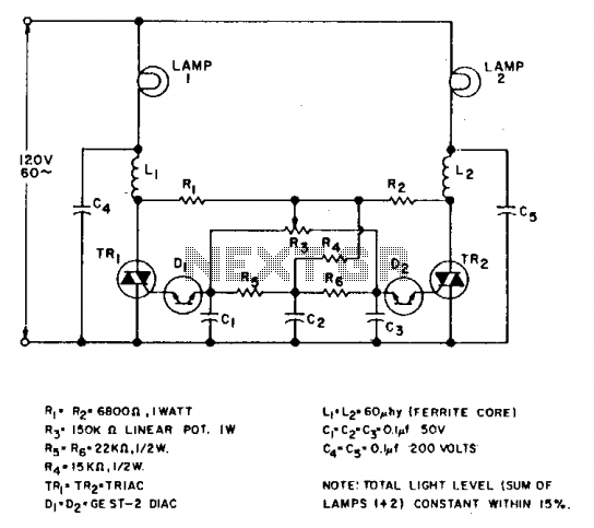
This cross fader circuit can be used for fading between two slide projectors. As R3 is moved to either side of center, one triac is fired earlier in each half c...
Triac lamp dimmer
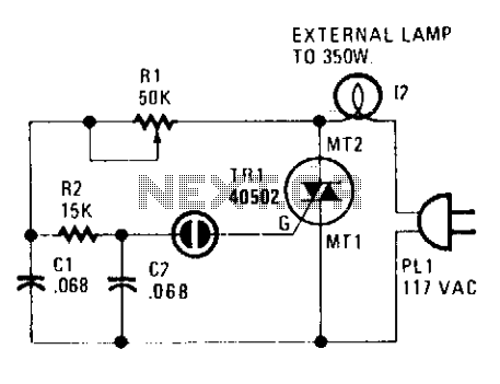
Using a heatsink, the TRIAC (TR1) can handle up to 350 watts. The neon lamp, II, won't trip the gate until after it conducts and using Rl, set the lighting wher...
Rugged lamp driver
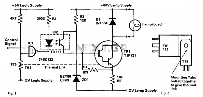
This circuit is capable of driving filament lamps of nominal rating 200 mA at 60 V dc from a CMOS logic signal. The lamp or load is connected in series with the...
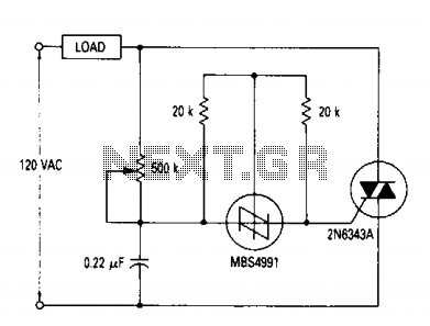
AC Lamp dimmer
A full range power controller suitable for lamp dimming and similar applications operate from a 120 volt, 60 Hz ac source, and can control up to 1000 watts of p...
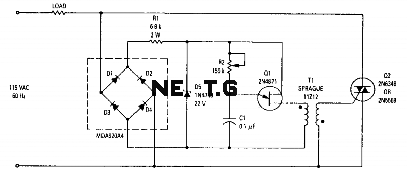
800Watt light-dimmer
This wide-range light dimmer circuit uses a unijunction transistor and a pulse transformer to provide phase control for the TRIAC. The circuit operates from a 1...
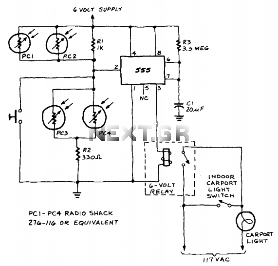
Auto light controller
A 555 timer IC, operating in the one-shot mode, is triggered by light striking photoresistors. These normally have a resistance of several megohms but, in the p...