


cable tester uses quad latch
#cable tester
#quad latch
#intermittent breaks
#microphone cables
#multimeter
#9V battery
#7805 regulator
#momentary contact
#push-button
#four cores
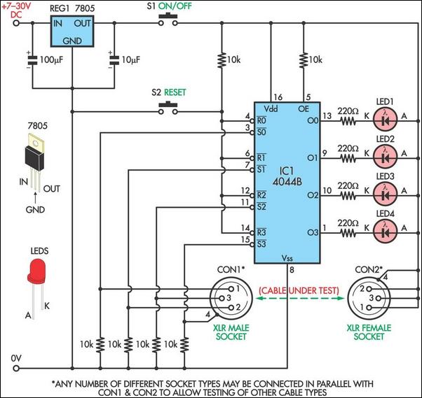
Description: This circuit is designed to facilitate the testing of microphone cables or other types of cables for intermittent breaks that are often challenging to detect with a multimeter. The circuit can accommodate cables with up to four cores. It employs two momentary contact push-button switches and can operate using a 9V battery, allowing for the omission of the 7805 voltage regulator. To test a cable, it is connected between two sockets, and pressing switch S2 resets all four latches in IC1, setting them to low. This action activates all four LEDs. A good connection for each core of the cable will pull the relevant Set inputs of the latches (pins 3, 7, 11, and 15) high, keeping the corresponding LED illuminated. Conversely, a broken connection in the cable will pull the relevant Set input low through the associated 10kΩ resistor, resulting in the LED turning off. The circuit's latching capability makes it straightforward to identify even minor breaks by flexing and twisting the cable along its length until one of the LEDs turns off. To accommodate different types of cables, appropriate sockets can be connected in parallel with or in place of the XLR sockets.
This cable testing circuit utilizes a systematic approach to identify faults within multi-core cables, particularly useful for audio applications. The core components include a microcontroller or latch IC (IC1), which is essential for maintaining the state of the outputs (LEDs) based on the input signals from the cable connections. The momentary contact push-button switch (S2) serves as a reset mechanism, enabling the user to initiate a fresh test cycle easily.
The circuit configuration allows for a straightforward connection of the cable under test between two designated sockets. Upon activation of switch S2, the latches are reset, and all four LEDs illuminate, indicating that the system is ready for testing. Each LED corresponds to a specific core of the cable, providing immediate visual feedback on the integrity of the connections.
In the event of a good connection, the relevant latches receive a high signal from the cable's core, which maintains the LED in an 'on' state. If a break occurs, the corresponding latches will receive a low signal due to the pull-down effect of the 10kΩ resistor, resulting in the LED turning off. This feature enables users to flex and twist the cable, allowing for dynamic testing that can reveal intermittent faults that may not be apparent under static conditions.
The circuit can be modified to test various cable types by replacing or adding appropriate sockets, thereby increasing its versatility. The design's simplicity and effectiveness make it an invaluable tool for audio technicians and engineers who require reliable cable testing solutions in their work.This circuit was designed to allow microphone cables or other cables to be easily tested for intermittent breaks that can often be difficult to find using a multimeter. The circuit can test cables with up to four cores. Both switches used in the circuit are momentary contact push-buttons and it can run from a 9V battery, in which case the 7805 reg
ulator can be omitted. To test a cable, connect it between the two sockets and press switch S2 which resets all four latches in IC1, setting them low. This turns on all four LEDs. A good connection for each core of the cable will mean that the relevant Set inputs of the latches (pins 3, 7, 11 & 15) will be pulled high and the appropriate LED will remain on.
A broken connection in the cable will result in the relevant Set input being pulled low by the associated 10k © resistor and the so the LED will be off. Because the circuit latches, it is easy to pinpoint even the smallest breaks by simply flexing and twisting the cable up and down its length until one of the LEDs turns off.
To test different types of cables, simply connect appropriate sockets in parallel with or in place of the XLR sockets.
This cable testing circuit utilizes a systematic approach to identify faults within multi-core cables, particularly useful for audio applications. The core components include a microcontroller or latch IC (IC1), which is essential for maintaining the state of the outputs (LEDs) based on the input signals from the cable connections. The momentary contact push-button switch (S2) serves as a reset mechanism, enabling the user to initiate a fresh test cycle easily.
The circuit configuration allows for a straightforward connection of the cable under test between two designated sockets. Upon activation of switch S2, the latches are reset, and all four LEDs illuminate, indicating that the system is ready for testing. Each LED corresponds to a specific core of the cable, providing immediate visual feedback on the integrity of the connections.
In the event of a good connection, the relevant latches receive a high signal from the cable's core, which maintains the LED in an 'on' state. If a break occurs, the corresponding latches will receive a low signal due to the pull-down effect of the 10kΩ resistor, resulting in the LED turning off. This feature enables users to flex and twist the cable, allowing for dynamic testing that can reveal intermittent faults that may not be apparent under static conditions.
The circuit can be modified to test various cable types by replacing or adding appropriate sockets, thereby increasing its versatility. The design's simplicity and effectiveness make it an invaluable tool for audio technicians and engineers who require reliable cable testing solutions in their work.This circuit was designed to allow microphone cables or other cables to be easily tested for intermittent breaks that can often be difficult to find using a multimeter. The circuit can test cables with up to four cores. Both switches used in the circuit are momentary contact push-buttons and it can run from a 9V battery, in which case the 7805 reg
ulator can be omitted. To test a cable, connect it between the two sockets and press switch S2 which resets all four latches in IC1, setting them low. This turns on all four LEDs. A good connection for each core of the cable will mean that the relevant Set inputs of the latches (pins 3, 7, 11 & 15) will be pulled high and the appropriate LED will remain on.
A broken connection in the cable will result in the relevant Set input being pulled low by the associated 10k © resistor and the so the LED will be off. Because the circuit latches, it is easy to pinpoint even the smallest breaks by simply flexing and twisting the cable up and down its length until one of the LEDs turns off.
To test different types of cables, simply connect appropriate sockets in parallel with or in place of the XLR sockets.
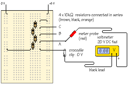
using a multimeter
A meter is a measuring instrument. An ammeter measures current, a voltmeter measures the potential difference (voltage) between two points, and an ohmmeter measures resistance. A multimeter combines these functions, and possibly some additional ones, into a single instrument. Before...
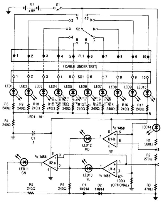
Cable Tester Circuit
The cable tester utilizes two operational amplifiers (op-amps) configured as window comparators to detect short or open circuit conditions. A third op-amp comparator is employed to indicate a properly functioning circuit, meaning it is neither open nor shorted. Colored light-emitting...
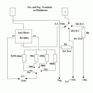
Basic Multimeter
A combination of shunts and multipliers, selected via a switch, can be utilized alongside a single basic meter to create a multirange instrument known as a multimeter. This device is capable of measuring voltage, current, and resistance. A multirange meter...
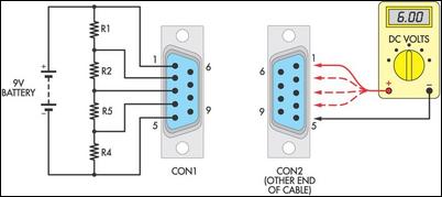
el cheapo cable tester
Many cable testers have been previously published, some of which are quite complex. However, here is a cost-effective and straightforward alternative. It utilizes only a 9V battery, two mating connectors, and several resistors, along with a multimeter for voltage measurements....
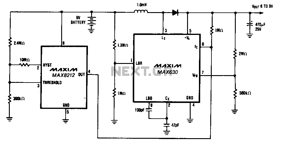
9-V-battery-life-extender
The circuit provides a minimum output of 7 V until the 9-V battery voltage drops below 2 V. When the battery voltage is above 7 V, the MAX630's IC pin is low, placing it in shutdown mode, which consumes only...

Multi Wire Cable Tester
A multi-wire cable tester features a separate LED indicator for each wire. It is capable of detecting open circuits, short circuits, reversals, earth faults, and continuity, utilizing four integrated circuits (ICs). Initially designed for intercom systems, it is also applicable...
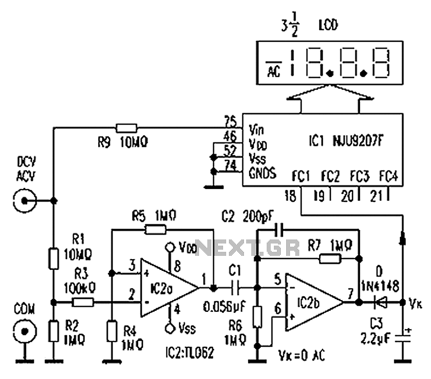
Multimeter AC DC converter circuit diagram automatically
The circuit depicted in the figure illustrates an automatic AC/DC converter for a digital multimeter. Typically, standard digital multimeters require manual intervention to switch between AC and DC measurements. The new DT860D digital multimeter utilizes the NJU9207F automatic range switching...
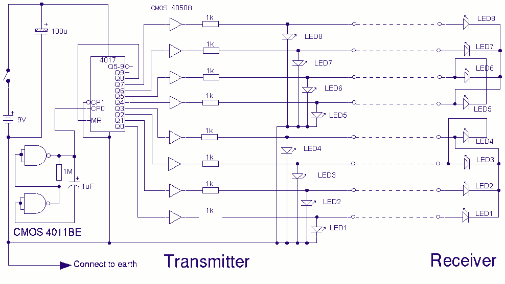
Multi Wire Cable Tester
A multi wire cable tester with a separate LED for each wire. Will show open circuits, short circuits, reversals, earth faults, continuity and all with four IC`s. Designed initially for my intercom, but can be used with alarm wiring, CAT...
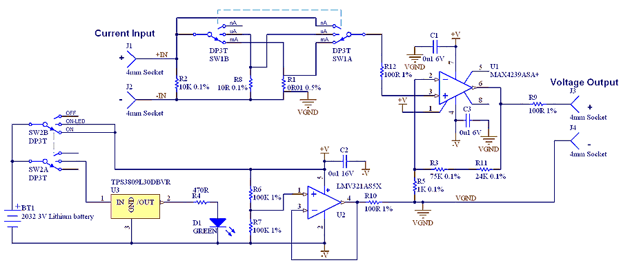
µCurrent Adaptor for multimeters
The µCurrent is in many cases also able to improve upon your meters current range accuracy by using your meters more accurate mVDC or mVAC voltage ranges instead to display the DC or AC current. With AC the frequency response...