


Linear RF Power Meter
#RF power meter
#LMV225
#SMD
#450 MHz to 2000 MHz
#linear IC
#input coupling capacitor
#DC voltage
#frequency range
#external components
#RF measurement
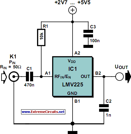
Description: The National Semiconductor LMV225 is a linear RF power meter integrated circuit (IC) housed in a surface-mount device (SMD) package. It operates within a frequency range of 450 MHz to 2000 MHz and requires only four external components for functionality. An input coupling capacitor serves to isolate the DC voltage of the IC from the incoming signal. A 10-kΩ resistor controls the enabling or disabling of the IC based on the DC voltage present at the input pin. When this voltage exceeds 1.8 V, the detector is activated, drawing approximately 58 mA of current. Conversely, if the voltage at pin A1 falls below 0.8 V, the IC enters shutdown mode, consuming only a few microamperes. The LMV225 can be toggled between active and shutdown modes using a logic-level signal connected through the 10-kΩ resistor. The supply voltage, which ranges from +2.7 V to +5.5 V, is filtered by a 100 nF capacitor that diverts any residual RF signals to ground. Additionally, an output capacitor forms a low-pass filter in conjunction with the internal circuitry of the LMV225. With a capacitance of 1 nF, the corner frequency of this low-pass filter is approximately 8 kHz, which can be calculated using the formula fc = 1/(2πCOUTRo), where Ro is the internal output impedance (19.8 kΩ). This output low-pass filter determines the AM modulation components that the detector allows to pass. The output, characterized by a relatively high impedance, yields a voltage that is proportional to the signal power, with a slope of 40 mV/dB. For instance, the output voltage is 2.0 V at 9 dBm and 0.4 V at 40 dBm. A level of 0 dBm corresponds to a power of 1 mW in a 50 Ω system, which is equivalent to an effective voltage of 224 mV for a sinusoidal waveform. For modulated signals, the relationship between power and voltage typically varies. The input impedance of the LMV225 detector is approximately 50 Ω, ensuring a good match to the characteristic impedance commonly found in RF circuits. The data sheet for the LMV225 indicates that the 40-dB measurement range can be adjusted to a higher power level through the use of a series input resistor. Originally designed for mobile phone applications, the LMV225 is compact, with an SMD package measuring approximately 1 mm x 1 mm and featuring four solder bumps similar to a ball-grid array package. The connections are labeled A1, A2, B1, and B2, resembling a matrix layout, with the corner adjacent to A1 being beveled.
The LMV225 is designed to facilitate precise RF power measurements, making it suitable for applications in various RF and communication systems. The integration of a low-pass filter at the output stage is crucial for minimizing high-frequency noise and ensuring that only the desired modulation components are processed. The ability to switch between active and shutdown modes enhances the versatility of the device, allowing it to conserve power when not in use, which is particularly beneficial in battery-operated devices.
Moreover, the compact SMD package enables easy integration into existing circuit designs without requiring significant board space, making it ideal for modern electronic applications. The specified input impedance of 50 Ω allows for seamless interfacing with standard RF components, ensuring optimal performance in signal detection and measurement tasks. The output characteristics, providing a linear relationship between output voltage and input power, facilitate straightforward interpretation of power levels, aiding in the design and troubleshooting of RF circuits.
Overall, the LMV225 serves as a critical component in RF power measurement applications, with its design tailored to meet the needs of contemporary mobile and wireless communication technologies. The detailed specifications and operational characteristics outlined in the data sheet provide essential guidance for engineers and designers aiming to implement this IC effectively in their projects.The National Semiconductor LMV225 is a linear RF power meter IC in an SMD package. It can be used over the frequency range of 450 MHz to 2000 MHz and requires only four external components. The input coupling capacitor isolates the DC voltage of the IC from the input signal. The 10-k resistor enables or disables the IC according to the DC voltage present at the input pin. If it is higher than 1. 8 V, the detector is enabled and draws a current of around 5 8 mA. If the voltage on pin A1 is less than 0. 8 V, the IC enters the shutdown mode and draws a current of only a few microampG¨res. The LMV225 can be switched between the active and shutdown states using a logic-level signal if the signal is connected to the signal via the 10-kR resistor. The supply voltage, which can lie between +2. 7 V und +5. 5 V, is filtered by a 100nF capacitor that diverts residual RF signals to ground. Finally, there is an output capacitor that forms a low-pass filter in combination with the internal circuitry of the LMV225.
If this capacitor has a value of 1 nF, the corner frequency of this low-pass filter is approximately 8 kHz. The corner frequency can be calculated using the formula fc = 1 G· (2 p COUT Ro) where Ro is the internal output impedance (19.
8 k ). The output low-pass filter determines which AM modulation components are passed by the detector. The output, which has a relatively high impedance, provides an output voltage that is proportional to the signal power, with a slope of 40 mV/dB. The output is 2. 0 V at 9 dBm and 0. 4 V at 40 dBm. A level of 0 dBm corresponds to a power of 1 mW in 50 R. For a sinusoidal wave-form, this is equivalent to an effective voltage of 224 mV. For modulated signals, the relationship between power and voltage is generally different. The table shows several examples of power levels and voltages for sinusoidal signals. The input impedance of the LMV225 detector is around 50 R to provide a good match to the characteristic impedance commonly used in RF circuits.
The data sheet for the LMV225 shows how the 40-dB measurement range can be shifted to a higher power level using a series input resistor. The LMV225 was originally designed for use in mobile telephones, so it comes in a tiny SMD package with dimensions of only around 1 G— 1 mm with four solder bumps (similar to a ball-grid array package).
The connections are labelled A1, A2, B1 and B1, like the elements of a matrix. The corner next to A1 is bevelled.
The LMV225 is designed to facilitate precise RF power measurements, making it suitable for applications in various RF and communication systems. The integration of a low-pass filter at the output stage is crucial for minimizing high-frequency noise and ensuring that only the desired modulation components are processed. The ability to switch between active and shutdown modes enhances the versatility of the device, allowing it to conserve power when not in use, which is particularly beneficial in battery-operated devices.
Moreover, the compact SMD package enables easy integration into existing circuit designs without requiring significant board space, making it ideal for modern electronic applications. The specified input impedance of 50 Ω allows for seamless interfacing with standard RF components, ensuring optimal performance in signal detection and measurement tasks. The output characteristics, providing a linear relationship between output voltage and input power, facilitate straightforward interpretation of power levels, aiding in the design and troubleshooting of RF circuits.
Overall, the LMV225 serves as a critical component in RF power measurement applications, with its design tailored to meet the needs of contemporary mobile and wireless communication technologies. The detailed specifications and operational characteristics outlined in the data sheet provide essential guidance for engineers and designers aiming to implement this IC effectively in their projects.The National Semiconductor LMV225 is a linear RF power meter IC in an SMD package. It can be used over the frequency range of 450 MHz to 2000 MHz and requires only four external components. The input coupling capacitor isolates the DC voltage of the IC from the input signal. The 10-k resistor enables or disables the IC according to the DC voltage present at the input pin. If it is higher than 1. 8 V, the detector is enabled and draws a current of around 5 8 mA. If the voltage on pin A1 is less than 0. 8 V, the IC enters the shutdown mode and draws a current of only a few microampG¨res. The LMV225 can be switched between the active and shutdown states using a logic-level signal if the signal is connected to the signal via the 10-kR resistor. The supply voltage, which can lie between +2. 7 V und +5. 5 V, is filtered by a 100nF capacitor that diverts residual RF signals to ground. Finally, there is an output capacitor that forms a low-pass filter in combination with the internal circuitry of the LMV225.
If this capacitor has a value of 1 nF, the corner frequency of this low-pass filter is approximately 8 kHz. The corner frequency can be calculated using the formula fc = 1 G· (2 p COUT Ro) where Ro is the internal output impedance (19.
8 k ). The output low-pass filter determines which AM modulation components are passed by the detector. The output, which has a relatively high impedance, provides an output voltage that is proportional to the signal power, with a slope of 40 mV/dB. The output is 2. 0 V at 9 dBm and 0. 4 V at 40 dBm. A level of 0 dBm corresponds to a power of 1 mW in 50 R. For a sinusoidal wave-form, this is equivalent to an effective voltage of 224 mV. For modulated signals, the relationship between power and voltage is generally different. The table shows several examples of power levels and voltages for sinusoidal signals. The input impedance of the LMV225 detector is around 50 R to provide a good match to the characteristic impedance commonly used in RF circuits.
The data sheet for the LMV225 shows how the 40-dB measurement range can be shifted to a higher power level using a series input resistor. The LMV225 was originally designed for use in mobile telephones, so it comes in a tiny SMD package with dimensions of only around 1 G— 1 mm with four solder bumps (similar to a ball-grid array package).
The connections are labelled A1, A2, B1 and B1, like the elements of a matrix. The corner next to A1 is bevelled.
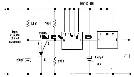
Dc Output Chopper Circuit
A direct current (DC) voltage source within the range of 2 to 15 volts can be converted into a unipolar square wave. This square wave has a peak amplitude that is nearly equal to the DC source voltage, with lightly...
Linear RF Power Meter
The National Semiconductor LMV225 is a linear RF power meter integrated circuit (IC) in a surface-mount device (SMD) package. It operates over a frequency range of 450 MHz to 2000 MHz.
The LMV225 is designed for precise measurement of radio frequency...
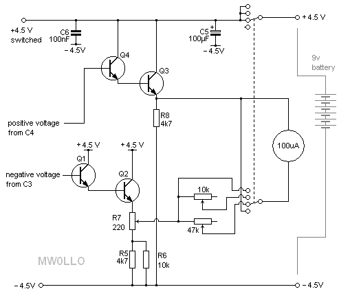
MW0LLO RF Milliwatt Meter
This project, based on an article published in the February 2008 edition of Radcom (the magazine of the Radio Society of Great Britain), describes a meter with a 50-ohm input impedance designed for measuring very small RF powers. Many RF...
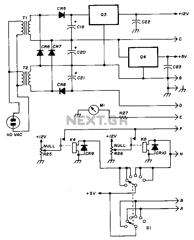
Wide-range-rf-power-meter
The Hewlett-Packard HSCH-3486 zero-bias Schottky diode is utilized as the detector. To avoid employing a modulation detection method, a chopper-stabilized operational amplifier is implemented. The chopper operational amplifier effectively converts the input DC voltage to AC, amplifies it, and then...
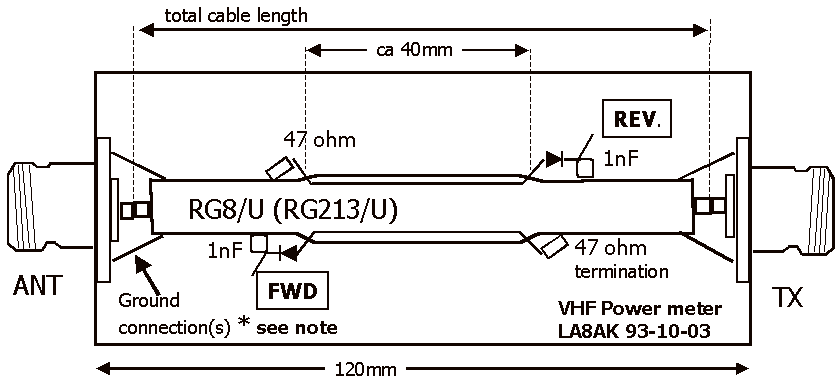
RF power and VSWR meter
The Inter-Power SWR-5 upper right isn't worth a penny. Got it from a mate to use with a beacon, but I burnt it out with only 3.5-4W morse signal on 70cm. Removed the bridge and installed my own pick-up line...
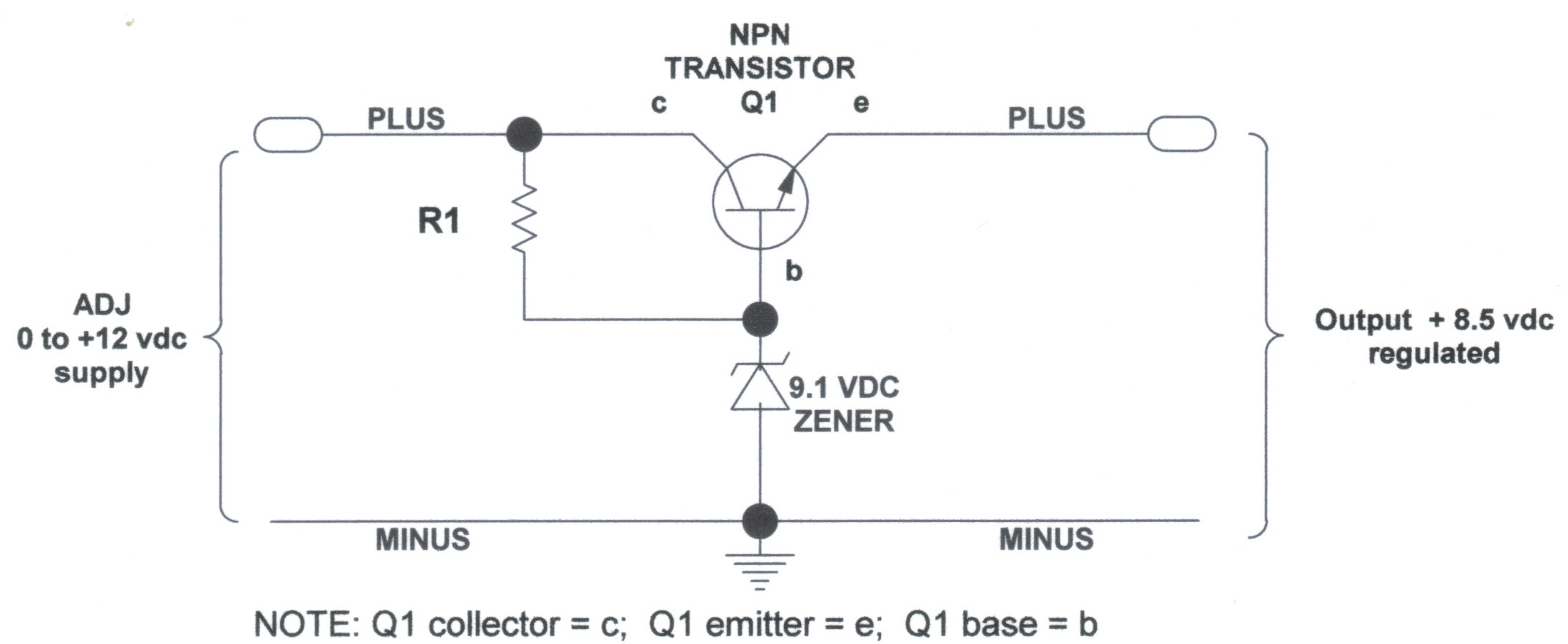
voltage regulators
DC Voltage Regulator (NPN & Zener Regulator) There are instances where it is handy to have a regulated DC voltage power supply for use on your model.
A DC voltage regulator is an essential component in electronic circuits that provides a...

SMD project
This is my first project with an SMD circuit. I previously avoided SMD components due to confusion caused by their small size. The circuit for the current SMD project involves headphones.
The project focuses on designing a compact headphone amplifier using...