


Mains Voltage Probe
#voltage probe
#LED indicator
#DC voltage
#AC voltage
#polarity detection
#simple circuit
#cheap circuit
#useful circuit
#mains voltage
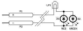
Description: This circuit is not a novelty, but it proved so useful, simple and cheap that it is worth building. When the positive (Red) probe is connected to a DC positive voltage and the Black probe to the negative, the Red LED will illuminate. Reversing polarities the Green LED will illuminate. Connecting the probes to an AC source both LEDs will go on. More: The bulb limits the LEDs current to 40mA @ 220V AC and its filament starts illuminating from about 30V, shining more brightly as voltage increases. Therefore, due to the bulb filament behavior, any voltage in the 1.8 to 230V range can be detected without.
This circuit functions as a simple voltage indicator, utilizing two Light Emitting Diodes (LEDs) and a bulb as a current limiter. The circuit is designed to provide visual feedback based on the polarity and type of voltage applied to the probes.
The circuit comprises a Red LED and a Green LED, which are connected in such a manner that the Red LED lights up when a positive DC voltage is detected at the positive probe (red) and the negative probe (black) is connected to ground or a negative supply. Conversely, when the polarity is reversed, the Green LED illuminates, indicating the presence of a negative voltage.
In the case of an AC voltage, both LEDs will activate simultaneously, providing a clear indication that alternating current is present. This dual LED configuration allows for quick identification of voltage type, which is particularly useful in troubleshooting electrical circuits.
The inclusion of a bulb in the circuit serves a dual purpose. Primarily, it acts as a current limiting device, ensuring that the LEDs do not exceed their maximum current rating of 40mA, especially when connected to high voltage AC sources up to 220V. The bulb's filament begins to glow at approximately 30V, which enhances the visual feedback of the circuit as the voltage increases. The filament's brightness correlates with the voltage level, allowing for a rough estimation of the voltage present.
This circuit is capable of detecting a voltage range from 1.8V to 230V, making it versatile for various applications. The simplicity and low cost of components make this circuit an attractive option for both hobbyists and professionals who require a straightforward voltage detection solution.This circuit is not a novelty, but it proved so useful, simple and cheap that it is worth building. When the positive (Red) probe is connected to a DC positive voltage and the Black probe to the negative, the Red LED will illuminate. Reversing polarities the Green LED will illuminate. Connecting the probes to an AC source both LEDs will go on. The bulb limits the LEDs current to 40mA @ 220V AC and its filament starts illuminating from about 30V, shining more brightly as voltage increases. Therefore, due to the bulb filament behavior, any voltage in the 1.8 to 230V range can be detected without
This circuit functions as a simple voltage indicator, utilizing two Light Emitting Diodes (LEDs) and a bulb as a current limiter. The circuit is designed to provide visual feedback based on the polarity and type of voltage applied to the probes.
The circuit comprises a Red LED and a Green LED, which are connected in such a manner that the Red LED lights up when a positive DC voltage is detected at the positive probe (red) and the negative probe (black) is connected to ground or a negative supply. Conversely, when the polarity is reversed, the Green LED illuminates, indicating the presence of a negative voltage.
In the case of an AC voltage, both LEDs will activate simultaneously, providing a clear indication that alternating current is present. This dual LED configuration allows for quick identification of voltage type, which is particularly useful in troubleshooting electrical circuits.
The inclusion of a bulb in the circuit serves a dual purpose. Primarily, it acts as a current limiting device, ensuring that the LEDs do not exceed their maximum current rating of 40mA, especially when connected to high voltage AC sources up to 220V. The bulb's filament begins to glow at approximately 30V, which enhances the visual feedback of the circuit as the voltage increases. The filament's brightness correlates with the voltage level, allowing for a rough estimation of the voltage present.
This circuit is capable of detecting a voltage range from 1.8V to 230V, making it versatile for various applications. The simplicity and low cost of components make this circuit an attractive option for both hobbyists and professionals who require a straightforward voltage detection solution.This circuit is not a novelty, but it proved so useful, simple and cheap that it is worth building. When the positive (Red) probe is connected to a DC positive voltage and the Black probe to the negative, the Red LED will illuminate. Reversing polarities the Green LED will illuminate. Connecting the probes to an AC source both LEDs will go on. The bulb limits the LEDs current to 40mA @ 220V AC and its filament starts illuminating from about 30V, shining more brightly as voltage increases. Therefore, due to the bulb filament behavior, any voltage in the 1.8 to 230V range can be detected without
voltage regulators
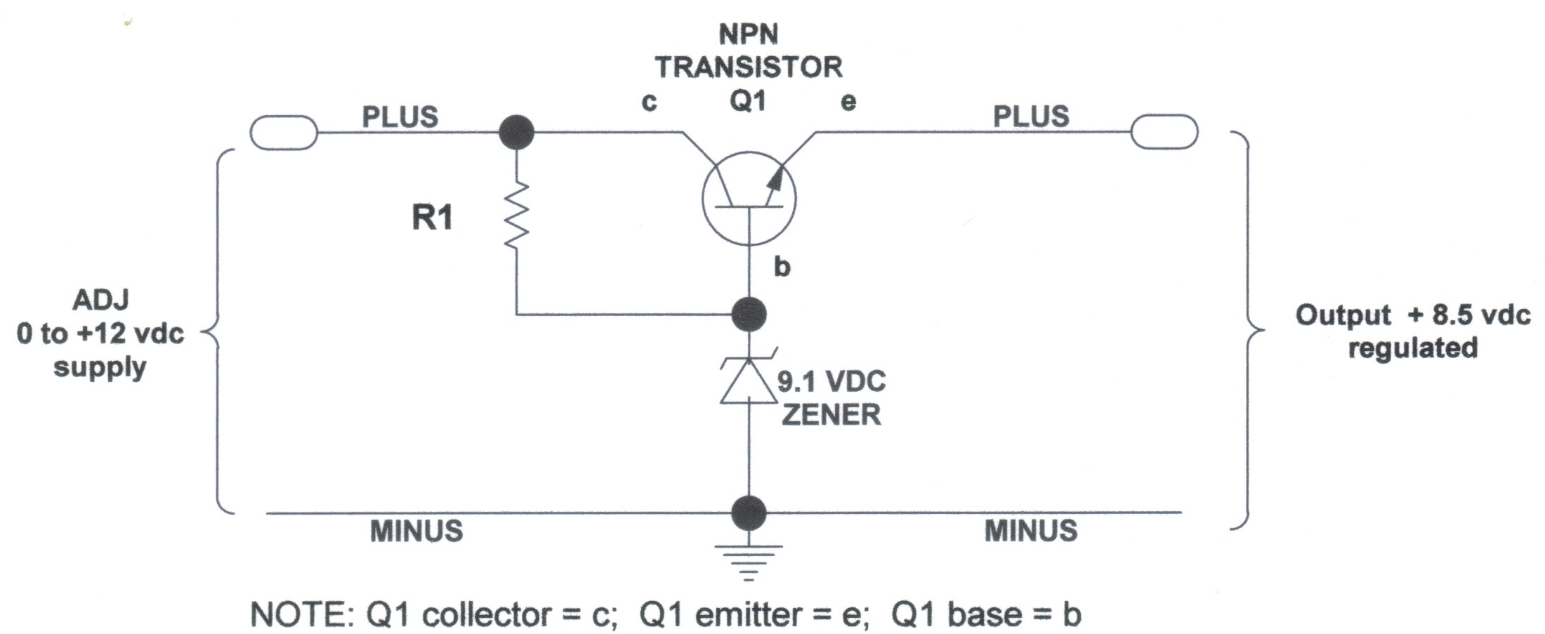
DC Voltage Regulator (NPN & Zener Regulator) There are instances where it is handy to have a regulated DC voltage power supply for use on your model.
A DC voltage regulator is an essential component in electronic circuits that provides a...
Voltage Test Probe
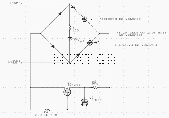
Using inexpensive components, you can fit a simple probe circuit into a pencil-sized enclosure. When both LEDs are on, the probe indicates the presence of an ac voltage; either LED alone indicates the presence and polarity of a dc voltage....
High/Low Voltage Probe
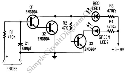
A simple voltage probe circuit is depicted in the schematic diagram below. This circuit is highly useful for testing or troubleshooting discrete or integrated circuits.
The simple voltage probe circuit serves as an essential tool for engineers and technicians engaged in...
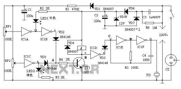
Mains voltage bidirectional limit alarm protection circuit diagram
The alarm protection can trigger a sound and light alert when the mains voltage exceeds or falls below a predetermined threshold. It automatically disconnects the electrical power supply without damaging the electrical protection. The device is compact, fully featured, and...
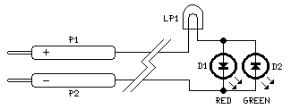
Ultra-simple Voltage Probe
This circuit is not a novelty, but it proved so useful, simple and cheap that it is worth building. When the positive (Red) probe is connected to a DC positive voltage and the Black probe to the negative, the Red...
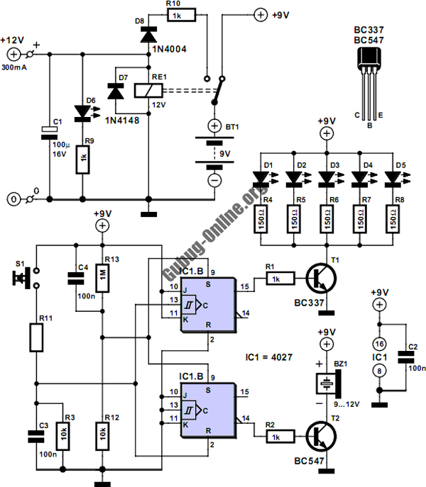
Mains Pulse Circuit
This circuit is designed to control the mains pulse. The pulser's purpose is to switch the mains voltage on and off at intervals ranging from just under one second to a maximum of ten minutes. This functionality is beneficial for...
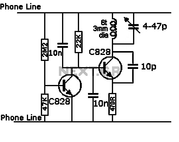
mains pulse circuit
This circuit is designed to control the mains voltage by switching it on and off at intervals ranging from just under a second to up to 10 minutes. It is particularly useful for testing mains-operated equipment over extended periods or...
Voltage Test Probe
Using inexpensive components, you can fit a simple probe circuit into a pencil-sized enclosure. When both LEDs are on, the probe indicates the presence of an ac voltage; either LED alone indicates the presence and polarity of a dc voltage....
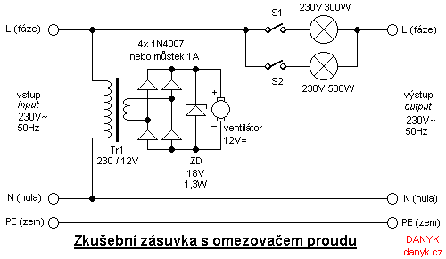
Test wall socket with current limiting
Individuals who frequently build, repair, and test equipment powered by mains voltage may encounter unexpected hazards, such as loud explosions, equipment destruction, flying components, tripped circuit breakers, and power outages. These incidents can be mitigated by utilizing a test wall...