


Phase sequence indicator
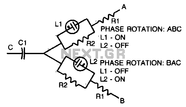
Description: A simple, portable phase-sequence indicator is designed to determine the correct phase rotation in polyphase circuits. The primary components include two neon lamps, two resistors, and a capacitor. During operation, the leg voltages are unbalanced, causing the lamp with the highest voltage—indicating the proper phase sequence—to illuminate.
The phase-sequence indicator operates by utilizing the characteristics of neon lamps, which only light up when the voltage across them exceeds a certain threshold. In a polyphase system, the voltage levels across the different phases can vary due to load imbalances or phase shifts. The two neon lamps in this circuit are connected in such a way that one will illuminate when the voltage on one phase is higher than the other, thus indicating the phase rotation.
The resistors in the circuit serve to limit the current flowing through the neon lamps, ensuring that they operate within their specified limits and preventing damage. The capacitor is used to stabilize the circuit by filtering out any high-frequency noise that may interfere with the reliable operation of the indicator.
Typical component values for the resistors and capacitor may vary depending on the frequency of the circuit being tested, as indicated in the accompanying table. For example, at lower frequencies, larger resistor values may be required to ensure proper operation, while at higher frequencies, smaller values may suffice. The selection of these components is critical to ensure accurate phase detection and to maintain the longevity of the device.
The overall design of the phase-sequence indicator is compact and portable, making it suitable for field applications where quick verification of phase rotation is necessary. This device is particularly useful for electricians and technicians working with three-phase systems, as incorrect phase rotation can lead to equipment damage or operational inefficiencies.Simple, portable phase-sequence indicator determines the proper phase rotation in polyphase circuits. Major components are two neon lamps, two resistors, and a capacitor. In operation, the leg voltages are unbalanced, so that the lamp with the maximum voltage—or proper phase sequence—lights
Table shows typical component values for various circuit frequencies.
The phase-sequence indicator operates by utilizing the characteristics of neon lamps, which only light up when the voltage across them exceeds a certain threshold. In a polyphase system, the voltage levels across the different phases can vary due to load imbalances or phase shifts. The two neon lamps in this circuit are connected in such a way that one will illuminate when the voltage on one phase is higher than the other, thus indicating the phase rotation.
The resistors in the circuit serve to limit the current flowing through the neon lamps, ensuring that they operate within their specified limits and preventing damage. The capacitor is used to stabilize the circuit by filtering out any high-frequency noise that may interfere with the reliable operation of the indicator.
Typical component values for the resistors and capacitor may vary depending on the frequency of the circuit being tested, as indicated in the accompanying table. For example, at lower frequencies, larger resistor values may be required to ensure proper operation, while at higher frequencies, smaller values may suffice. The selection of these components is critical to ensure accurate phase detection and to maintain the longevity of the device.
The overall design of the phase-sequence indicator is compact and portable, making it suitable for field applications where quick verification of phase rotation is necessary. This device is particularly useful for electricians and technicians working with three-phase systems, as incorrect phase rotation can lead to equipment damage or operational inefficiencies.Simple, portable phase-sequence indicator determines the proper phase rotation in polyphase circuits. Major components are two neon lamps, two resistors, and a capacitor. In operation, the leg voltages are unbalanced, so that the lamp with the maximum voltage—or proper phase sequence—lights
Table shows typical component values for various circuit frequencies.
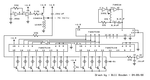
12 stage neon sequencer ne 2 ne 51
This circuit resembles an LED clock, utilizing 12 neon indicator lamps in place of LEDs. It operates on two high-capacity nickel-cadmium (Ni-Cad) cells providing 2.5 volts, allowing sustained operation for several weeks. The high voltage (70 volts) required for the...
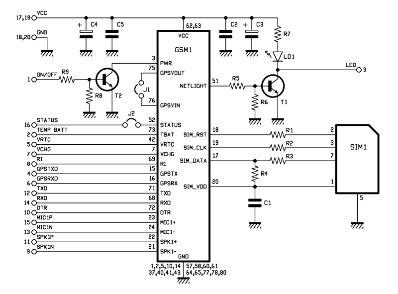
Help me Understand this Circuit Schematic
The roles of capacitors C1, C4, and C5 in a circuit may not be immediately clear. Capacitors on the power rail help to smooth out the signal by reducing current ripple, which can be observed using an oscilloscope. Resistors R6...

adj pwr
The design incorporates a universal capacitor mounting and spacing feature, enabling compatibility with various capacitor types. It includes a mounting pattern suitable for TO-200 or TO-218/247 packages, specifically for the pass transistor and the transistor utilized in the current limit...
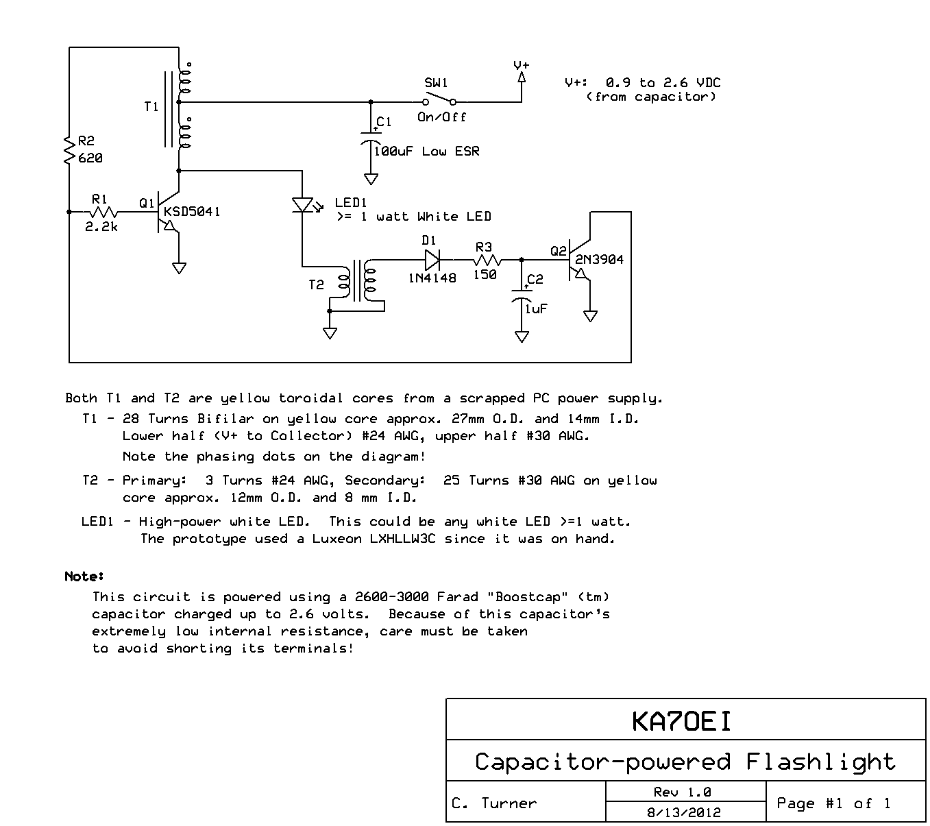
a more practical capacitor powered
The inexpensive flashlight utilized a small (0.22 Farad) capacitor for energy storage, which provided approximately 6.6 Joules of energy, significantly less than 1/1000th of the energy contained in a single AA alkaline cell. As a standard "super capacitor," it had...
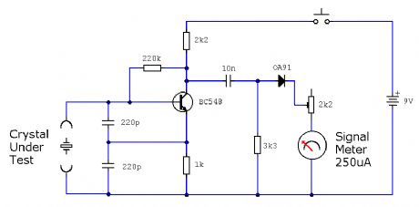
ELF MONITOR
The capacitor instrument is not intended for measuring the capacitance of capacitors; rather, it is designed to identify whether a capacitor is functional or defective, as well as to detect short circuits or open circuits. This functionality provides reliable quality...
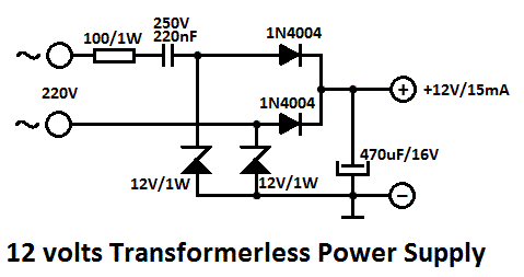
Capacitor Power Supply Circuit
One of the major problems that must be addressed in electronic circuit design is the generation of low voltage DC power supply from mains power to energize the circuit.
In electronic circuit design, the conversion of mains AC voltage to a...
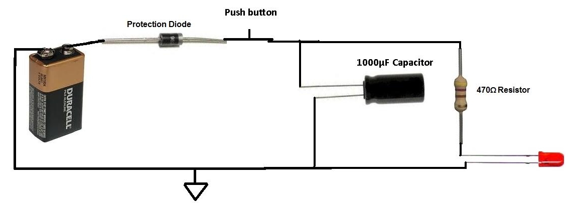
Charged Capacitor to Light an LED
This project involves charging a capacitor with voltage, which will subsequently serve as a temporary power source for the circuit. After charging the capacitor with a battery, the battery is disconnected from the circuit. The capacitor then provides current to...
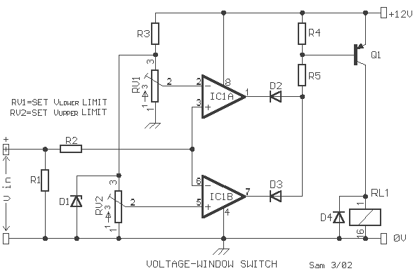
Voltage window switch
A voltage window switch is in practice the basic lower window limit of this circuit is roughly 3V and the upper limit is 9V. The window range can be extended by fitting a suitable range
Part List
R1-2=10Kohm D1=9V1/ 0.5W Zener IC1=TL072...
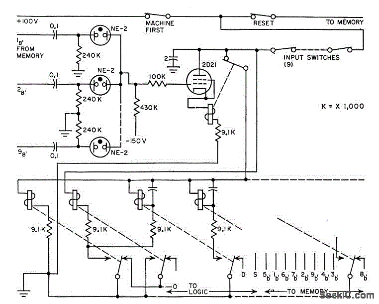
TICK TACK TOE LOGIC
Neon lamps function as diode gates and indicate positions and moves on a game board. The thyratron-relay combination acts as memory, while relays manage the sequence to prevent two successive moves by either player.
Neon lamps are utilized in this...