


Insect Repellant
#insect repellant
#phase locked loop
#CMOS 4047
#22KHz oscillator
#complimentary output transistors
#piezo
#external power supply
#Graham Maynard
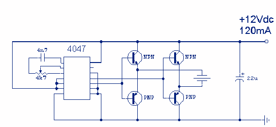
Description: Repell those repugnant insects from your Garden this Summer with this insect repellant circuit. Designed by Graham Maynard, the circuitry consists of a phase locked loop (CMOS 4047) wired as a 22KHz oscillator. The output is amplified by a pair of complimentary output transistors and drives a Motorola 3.25 inch Piezo. Current drain is around 120mA so an external power supply is recommended. More: The piezo used was a standard 85mm square Motorola Horn, Maplin part number WF09K or WF55K. These are rated +/-3dB to 28kHz.
The insect repellant circuit operates primarily by generating ultrasonic sound waves that are unpleasant to insects, effectively deterring them from the area. The heart of the circuit is the CMOS 4047 phase-locked loop, configured to function as an oscillator producing a frequency of 22 kHz. This frequency is above the range of human hearing but within the sensitivity range of many insect species.
The output from the 4047 is a square wave signal, which is then fed into a pair of complementary output transistors. These transistors serve to amplify the signal, ensuring that sufficient power is delivered to the piezoelectric transducer. The choice of a Motorola 3.25-inch piezo horn allows for effective sound projection, leveraging its design to emit sound waves efficiently across a wider area.
The circuit is designed to operate with a current drain of approximately 120mA, necessitating an external power supply to ensure stable operation. It is advisable to use a regulated power source to maintain consistent output and prevent any fluctuations that could affect performance.
The piezo used in this circuit is a standard 85mm square Motorola Horn, specifically part numbers WF09K or WF55K. These components have a frequency response rated at +/-3dB up to 28 kHz, which makes them suitable for this application, as they can effectively produce the desired ultrasonic frequencies while maintaining clarity and volume.
In summary, this insect repellant circuit effectively combines a CMOS oscillator with a robust amplification stage and a high-performance piezo transducer, creating a reliable solution for deterring unwanted insects in garden environments.Repell those repugnent insects from your Garden this Summer with this insect repellant circuit. Designed by Graham Maynard the circuitry consists of a phase locked loop (CMOS 4047) wired as a 22KHz oscillator. The output is amplified by a pair of complimentary output transistors and drives a Motorola 3.25 inch Piezo.
Current drain is around 120mA so an external power supply is recommended. The piezo used was a standard 85mm square Motorola Horn, Maplin part number WF09K or WF55K. These are rated+/-3dB to 28kHz.
The insect repellant circuit operates primarily by generating ultrasonic sound waves that are unpleasant to insects, effectively deterring them from the area. The heart of the circuit is the CMOS 4047 phase-locked loop, configured to function as an oscillator producing a frequency of 22 kHz. This frequency is above the range of human hearing but within the sensitivity range of many insect species.
The output from the 4047 is a square wave signal, which is then fed into a pair of complementary output transistors. These transistors serve to amplify the signal, ensuring that sufficient power is delivered to the piezoelectric transducer. The choice of a Motorola 3.25-inch piezo horn allows for effective sound projection, leveraging its design to emit sound waves efficiently across a wider area.
The circuit is designed to operate with a current drain of approximately 120mA, necessitating an external power supply to ensure stable operation. It is advisable to use a regulated power source to maintain consistent output and prevent any fluctuations that could affect performance.
The piezo used in this circuit is a standard 85mm square Motorola Horn, specifically part numbers WF09K or WF55K. These components have a frequency response rated at +/-3dB up to 28 kHz, which makes them suitable for this application, as they can effectively produce the desired ultrasonic frequencies while maintaining clarity and volume.
In summary, this insect repellant circuit effectively combines a CMOS oscillator with a robust amplification stage and a high-performance piezo transducer, creating a reliable solution for deterring unwanted insects in garden environments.Repell those repugnent insects from your Garden this Summer with this insect repellant circuit. Designed by Graham Maynard the circuitry consists of a phase locked loop (CMOS 4047) wired as a 22KHz oscillator. The output is amplified by a pair of complimentary output transistors and drives a Motorola 3.25 inch Piezo.
Current drain is around 120mA so an external power supply is recommended. The piezo used was a standard 85mm square Motorola Horn, Maplin part number WF09K or WF55K. These are rated+/-3dB to 28kHz.
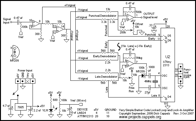
Locked Loop Synchronous Demodulator
A simple, low component count phase locked loop that locks onto and detects the amplitude of an incoming baseband 7 bit Barker code using a switched resistor demodulator that is driven directly by a microcontroller's output pins. Balanced modulators using...
phase locked loop pll oscillator
This 860 MHz Phase Locked Loop (PLL) oscillator circuit is designed for a 1200 MHz transverter's local oscillator with 435 MHz rigs. The oscillator circuit utilizes Toshiba PLL synthesizer ICs. The TC9122P is a user-friendly preset counter for determining the...
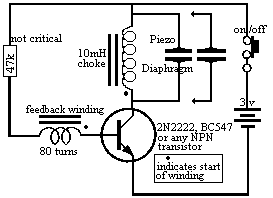
MINI PIEZO SIREN circuit
The piezo diaphragm can originate from a music card, and if two or three diaphragms are available, they can be connected in parallel, as illustrated in the diagram, to observe their impact on the output frequency. The only component that...
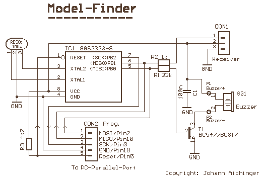
Air Model Finder
This simple circuit produces a loud trilling noise if no valid transmitter signal is received. This frequency must correspond with the resonant frequency of the piezo element; otherwise, the sound level will be very low. More: When you switch off...

precision phase locked loop circuit
The precision Phase Locked Loop (PLL) in this circuit operates similarly to a basic PLL, but with several enhancements. The flip-flops in the detector are equipped with a gate G1 to clear them, allowing for a faster response. The currents...
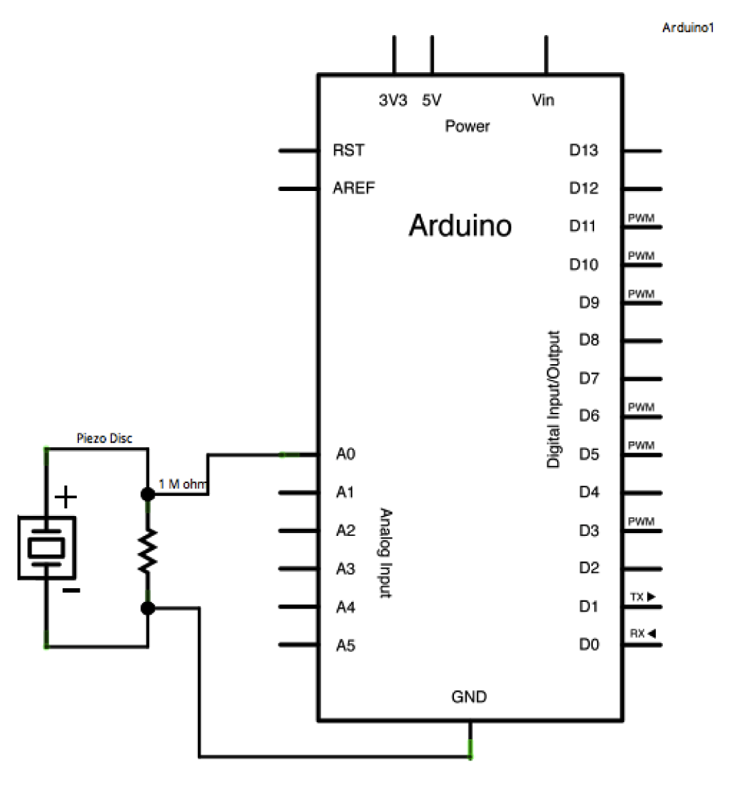
Arduino Knock
A piezo is an electronic device that generates a voltage when it is physically deformed by vibration, sound waves, or mechanical strain. Conversely, when a voltage is applied to a piezo, it vibrates and produces a tone. Piezos can be...
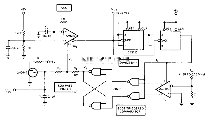
Full-band phase locked loop circuit diagram fast
A circuit diagram of a phase-locked loop utilizes an AM686 latched comparator as a voltage-controlled oscillator, along with a TTL latch connected to generate edge-triggered comparators. The VCO and its comparison with the low-pass filter consisting of R1, R2, and...
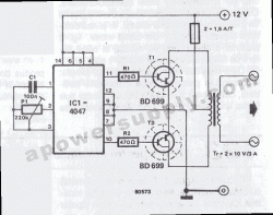
cmos 4047 power inverter 12vdc
This converter features a central component, the CMOS 4047, which converts a 12V DC voltage into a 220V AC voltage. The 4047 operates as an astable multivibrator. At pins 10 and 11, a symmetrical rectangular signal is generated, which is...
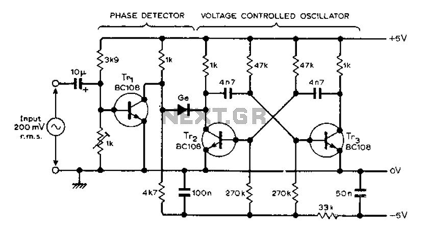
AF locked loop circuit diagram
The circuit MVBR utilizes a traditional two-transistor configuration along with other components to create a simple phase-locked loop (PLL). The transistor TR1 and diodes function as a logic gate, activating during half periods of the input waveform of the voltage-controlled...