


Delta connection Motor phase protection circuit
#delta connection
#motor phase protection
#phase failure
#protection circuit
#artificial neutral point
#resistors
#three-phase motor
#safety circuit
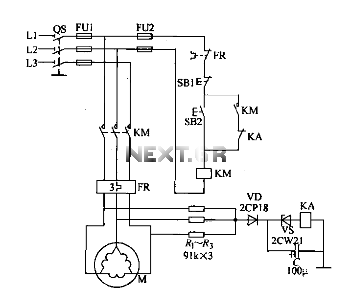
Description: Delta connection motor phase failure protection circuit is illustrated in the figure. Its protective function involves three resistors, R1, R2, and R3, which are connected to form an artificial neutral point. When a motor phase failure occurs, an offset at this neutral point is detected, causing relay KA to energize. As a result, the normally closed contacts of the relay open, interrupting the power to the contactor coil KM. This loss of power deactivates the motor circuit, effectively stopping the motor M.
The delta connection motor phase failure protection circuit is designed to safeguard three-phase induction motors from potential damage due to phase loss. The configuration utilizes three resistors, R1, R2, and R3, which are strategically connected to create an artificial neutral point. This neutral point serves as a reference for detecting phase imbalances.
In normal operating conditions, the voltage levels across the three phases remain balanced, and the artificial neutral point remains stable. However, when a phase failure occurs—meaning one of the phases experiences a drop in voltage or becomes completely disconnected—the balance is disrupted. This imbalance causes a shift in the voltage at the artificial neutral point, which is monitored by the relay KA.
Upon detecting this voltage shift, relay KA is activated. The activation of relay KA results in the opening of its normally closed contacts, which are connected to the contactor coil KM. This interruption effectively cuts off the power supply to the contactor coil, leading to the de-energization of the contactor. As a consequence, the main circuit supplying power to the motor M is also interrupted, thereby stopping the motor from running.
This phase failure protection mechanism is critical in preventing motor damage that could arise from prolonged operation under phase loss conditions. By automatically disconnecting the motor from the power supply, the circuit ensures that the motor does not overheat or suffer mechanical stress due to unbalanced loading. Overall, the delta connection motor phase failure protection circuit is a vital component in industrial motor control systems, enhancing reliability and safety in operations.Delta connection Motor phase failure protection circuit as shown in FIG. Its protective role is as follows: The three resistors R, ~ R3 connected as an artificial neutral point - when the motor phase failure, this neutral point offset occurs, relay KA is energized, normally closed relay contacts off contactor coil KM circuit. KM loss of power release motor circuit knock off the main circuit, the motor M is stopped.
The delta connection motor phase failure protection circuit is designed to safeguard three-phase induction motors from potential damage due to phase loss. The configuration utilizes three resistors, R1, R2, and R3, which are strategically connected to create an artificial neutral point. This neutral point serves as a reference for detecting phase imbalances.
In normal operating conditions, the voltage levels across the three phases remain balanced, and the artificial neutral point remains stable. However, when a phase failure occurs—meaning one of the phases experiences a drop in voltage or becomes completely disconnected—the balance is disrupted. This imbalance causes a shift in the voltage at the artificial neutral point, which is monitored by the relay KA.
Upon detecting this voltage shift, relay KA is activated. The activation of relay KA results in the opening of its normally closed contacts, which are connected to the contactor coil KM. This interruption effectively cuts off the power supply to the contactor coil, leading to the de-energization of the contactor. As a consequence, the main circuit supplying power to the motor M is also interrupted, thereby stopping the motor from running.
This phase failure protection mechanism is critical in preventing motor damage that could arise from prolonged operation under phase loss conditions. By automatically disconnecting the motor from the power supply, the circuit ensures that the motor does not overheat or suffer mechanical stress due to unbalanced loading. Overall, the delta connection motor phase failure protection circuit is a vital component in industrial motor control systems, enhancing reliability and safety in operations.Delta connection Motor phase failure protection circuit as shown in FIG. Its protective role is as follows: The three resistors R, ~ R3 connected as an artificial neutral point - when the motor phase failure, this neutral point offset occurs, relay KA is energized, normally closed relay contacts off contactor coil KM circuit. KM loss of power release motor circuit knock off the main circuit, the motor M is stopped.
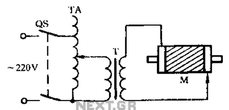
Check the three-phase motor with broken bars
The circuit diagram illustrates a three-phase motor equipped with an inspection circuit designed to detect broken bars.
The circuit for a three-phase motor with a broken bar inspection system typically consists of several key components that work together to monitor the...
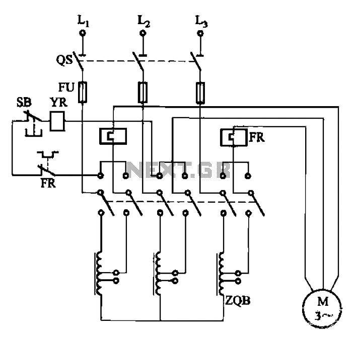
QJ3 series of manually operated auto-voltage start-up circuit
The circuit illustrated in Figure 3-47 involves a three-phase AC motor that is initially connected through a step-down autotransformer. To initiate operation, the power switch is closed, and the operating handle is pushed to the start position. Once the motor...

Three-phase squirrel cage motor running single phase connection circuit
The circuit connection is illustrated in figures a and b. In figure a, a star-shaped winding is used with shunt capacitance, while figure b depicts a triangular winding with capacitance connected in parallel. The working capacitance (Cc) is calculated using...
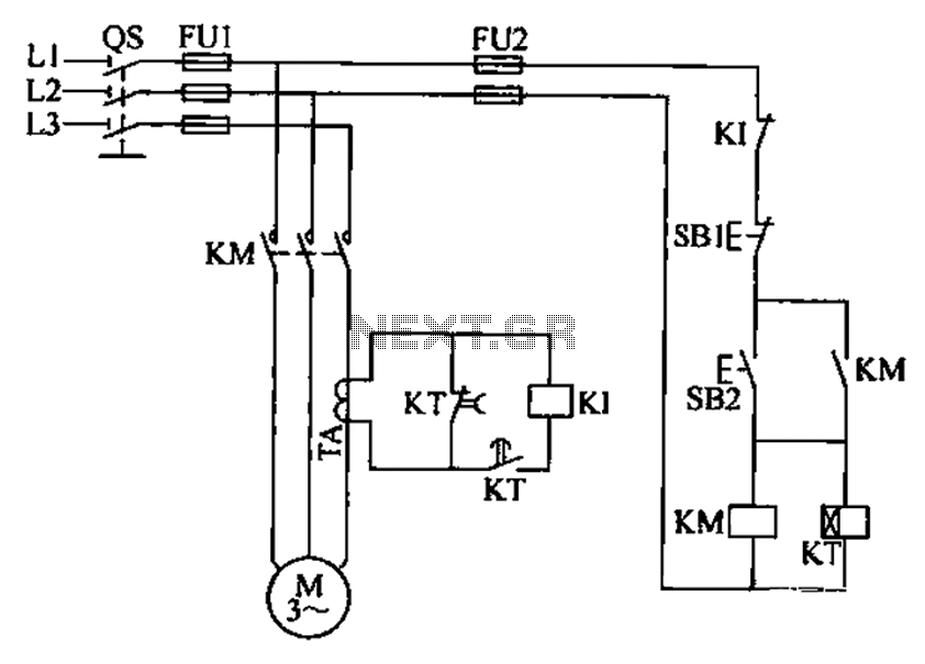
Three-phase motor overcurrent protection circuit
A three-phase electric motor overcurrent protection circuit. This example circuit utilizes a transformer to monitor the current, ensuring that the currents in the three-phase motor do not exceed normal operating levels. When the current exceeds the set threshold, the overcurrent...
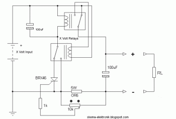
Electronic Fuse for DC Short Circuit Protection
This circuit is designed to protect a power supply or battery. The electric current will be interrupted by a relay when a short circuit occurs. Relays must be selected with a voltage rating equal to the input voltage. It is...
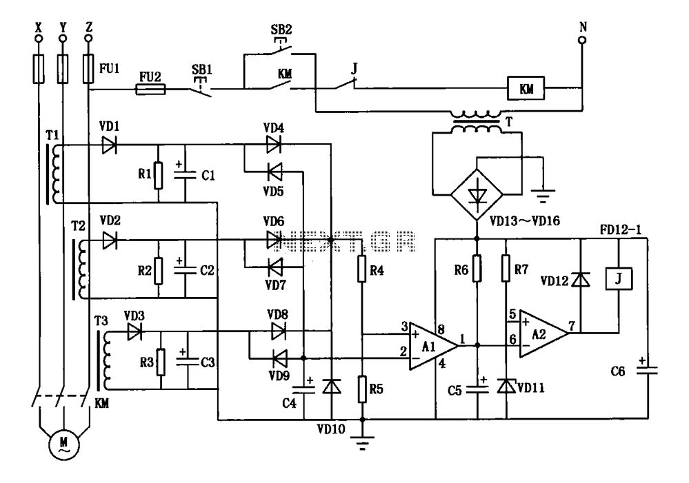
Current three-phase motor phase protection circuit diagram
A current three-phase motor phase protection circuit is designed to detect three-phase current using homemade small current transformers T1, T2, and T3. The current signals are collected by rectifiers VD1, VD2, and VD3, while capacitors C1, C2, and C3 serve...
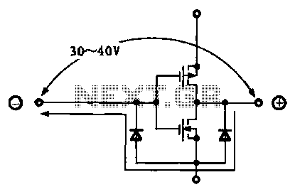
Various protection circuit structure and working principle diagram
Due to the varying conditions of different input signals, when an abnormal voltage is applied to the pin, protection circuits are designed to create a circuit path that secures the internal protection of large-scale integration (LSI) circuits. The structure and...
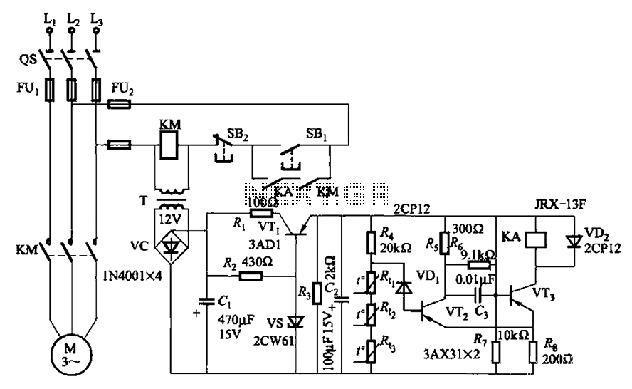
Three-phase asynchronous motor PTC protection circuits
A P-type transistor (VT2, VT3) and other components form a common emitter-coupled trigger, functioning as a Schmitt trigger device. This setup serves as a switching circuit to detect changes in the resistance of a PTC thermistor, thereby controlling the action...
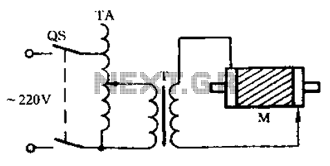
Check the circuit diagram of a three-phase motor with broken bars
Check the three-phase motor with broken bars as shown in the inspection circuit for the three-phase motor with broken bars.
The inspection circuit for a three-phase motor with broken bars is designed to diagnose and evaluate the condition of the motor's...