


The use of FR-FG and FR-AL achieve multiple synchronous motor running circuit
#Mitsubishi inverter
#FR-FG
#FR-AL
#synchronous motor
#speed setting
#linkage setting
#multi motors
#industrial automation
#motor synchronization
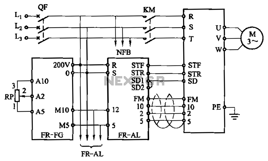
Description: The main speed setting box FR-FG and the linkage setting operation box FR-AL (Mitsubishi inverter) enable synchronous operation of multiple motors. The circuit is illustrated. By utilizing these two external units, the speed of the primary motor (main motor rotation speed) can be easily adjusted, ensuring that the speeds of the other motors remain consistent with it.
The described circuit facilitates the synchronous operation of multiple motors using the Mitsubishi inverter's FR-FG and FR-AL boxes. The FR-FG serves as the primary speed controller, allowing for real-time adjustments to the main motor's rotation speed. This is crucial in applications where precise synchronization between multiple motors is required, such as in conveyor systems, robotic arms, or multi-axis machining tools.
The FR-AL linkage setting operation box complements the FR-FG by providing a means to link the speed settings of additional motors to the primary motor. This ensures that any adjustments made to the primary motor's speed are automatically reflected in the operation of the secondary motors, maintaining a consistent operational speed across all units.
The circuit typically includes feedback mechanisms to monitor the speed of each motor, ensuring that they remain synchronized even under varying load conditions. This can be accomplished using tachometers or encoders that provide real-time feedback to the inverter system. Additionally, safety features should be integrated into the circuit design to prevent overloading and ensure reliable operation.
In summary, the integration of the FR-FG and FR-AL boxes in the circuit design allows for efficient and synchronized control of multiple motors, enhancing operational efficiency and reliability in various industrial applications. By the main speed setting box FR-FG and the linkage setting operation box FR-AL (Mitsubishi inverter) multi motors synchronous operation. Circuit is shown. Using these two exte rnal units, you can easily adjust the speed of the primary (main motor rotation speed), and the rest of the motor speed speed consistent with this.
The described circuit facilitates the synchronous operation of multiple motors using the Mitsubishi inverter's FR-FG and FR-AL boxes. The FR-FG serves as the primary speed controller, allowing for real-time adjustments to the main motor's rotation speed. This is crucial in applications where precise synchronization between multiple motors is required, such as in conveyor systems, robotic arms, or multi-axis machining tools.
The FR-AL linkage setting operation box complements the FR-FG by providing a means to link the speed settings of additional motors to the primary motor. This ensures that any adjustments made to the primary motor's speed are automatically reflected in the operation of the secondary motors, maintaining a consistent operational speed across all units.
The circuit typically includes feedback mechanisms to monitor the speed of each motor, ensuring that they remain synchronized even under varying load conditions. This can be accomplished using tachometers or encoders that provide real-time feedback to the inverter system. Additionally, safety features should be integrated into the circuit design to prevent overloading and ensure reliable operation.
In summary, the integration of the FR-FG and FR-AL boxes in the circuit design allows for efficient and synchronized control of multiple motors, enhancing operational efficiency and reliability in various industrial applications. By the main speed setting box FR-FG and the linkage setting operation box FR-AL (Mitsubishi inverter) multi motors synchronous operation. Circuit is shown. Using these two exte rnal units, you can easily adjust the speed of the primary (main motor rotation speed), and the rest of the motor speed speed consistent with this.
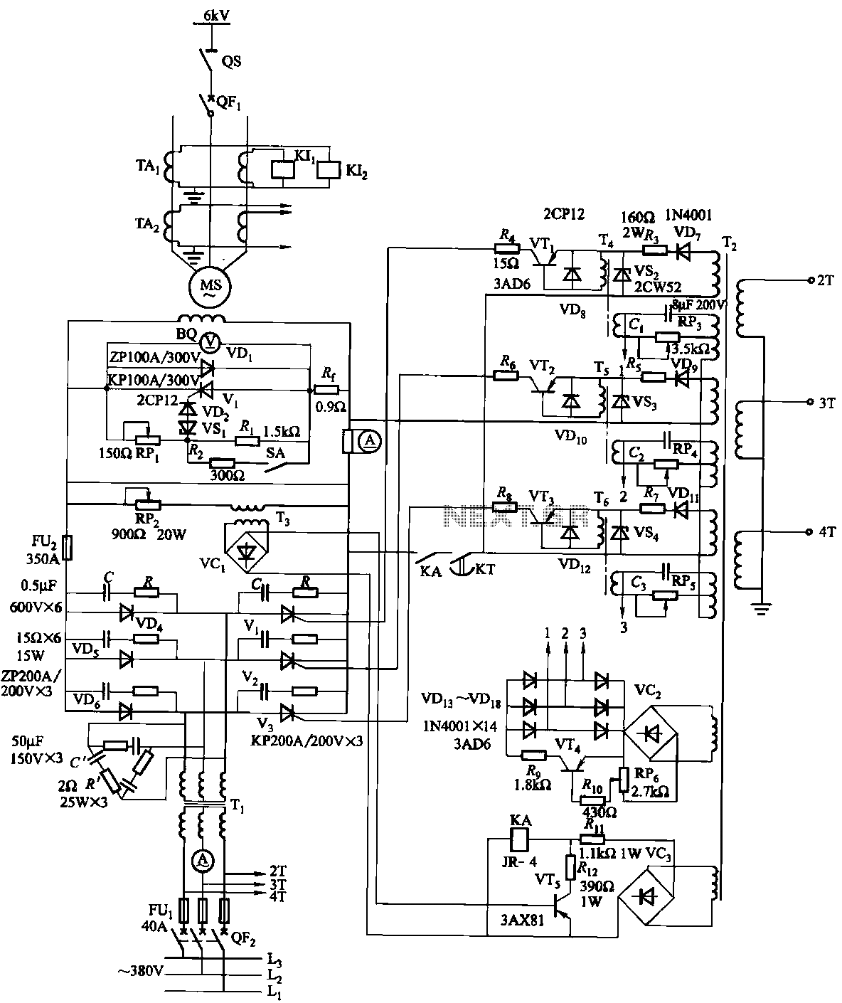
Synchronous motor thyristor excitation circuit
The excitation device for a light-duty synchronous motor rated at 625 kW has been initiated. The triggering circuit of the device consists of three identical RC phase-shift flip-flops. Adjustment potentiometers RP3 to RPs are used to set the RC phase...
Industrial-Automation
There are three controls that need to be adjusted for a proportional flow controller to function correctly. This process requires practice, and the experience gained can lead to stable control of the flow or velocity of a fluid. The actual...
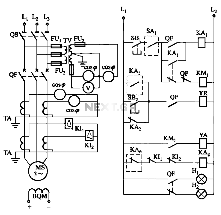
Synchronous motor full voltage start-up circuit
The circuit depicted in Figure 3-186 includes an isolation switch, QF vacuum circuit breakers, YR line for the circuit breaker coil, and YA for the circuit breaker closing coil. Additionally, there is a dashed box representing the excitation device (not...
Synchronous motor thyristor excitation circuit
The excitation device for a light-duty synchronous motor rated at 625 kW has been initiated. The triggering circuit of the device consists of three identical RC phase-shift flip-flops. Adjustment potentiometers RP3 to RPs are used to set the RC phase...
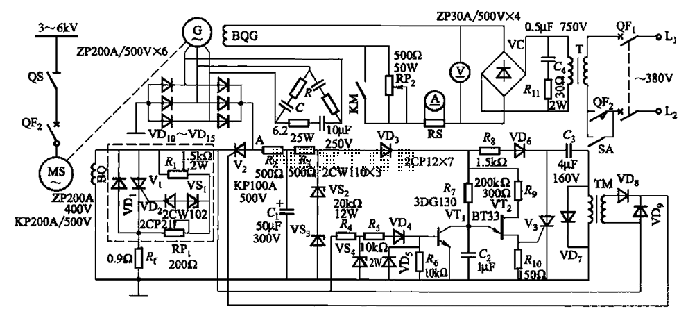
One synchronous motor thyristor excitation circuit
The circuit depicted in Figure 16-105 illustrates a synchronous motor. The components include BQ, which represents its field winding, and G, which denotes the AC excitation for the motor. The notation BQG indicates the field winding, with an empty box...