

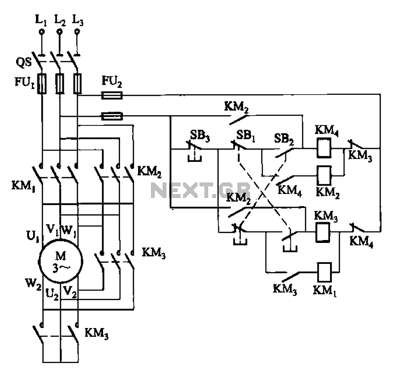

33kW and above windlass with Y- transfer power-saving circuit
33kW and above windlass with Y- conversion power-saving circuit ...
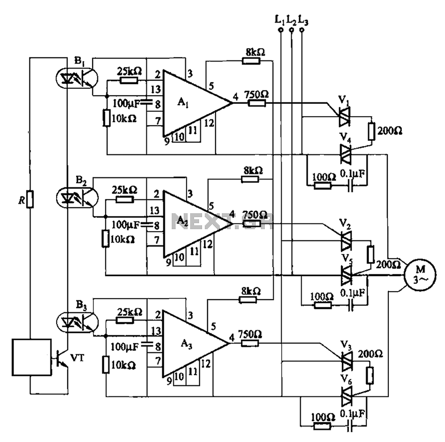
Thyristor controlled forward start circuit
331 circuit shown in FIG. It uses two-way thyristor controlled motor start and stop. It has no contact, no noise sound, no spark, etc., suitable for frequent op...
Thyristor controlled forward start circuit
331 circuit shown in FIG. It uses two-way thyristor controlled motor start and stop. It has no contact, no noise sound, no spark, etc., suitable for frequent op...
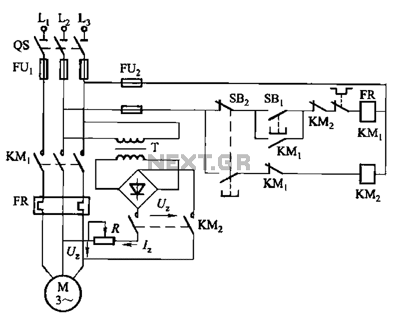
One-way operation of a dynamic braking circuit
3133 circuit shown in FIG. Figure 3-133 (a), dynamic braking (b), (c) the three lines by manually (button) control. Wherein FIG. (A), (b) the dynamic braking DC...
One-way operation of a dynamic braking circuit
3133 circuit shown in FIG. Figure 3-133 (a), dynamic braking (b), (c) the three lines by manually (button) control. Wherein FIG. (A), (b) the dynamic braking DC...
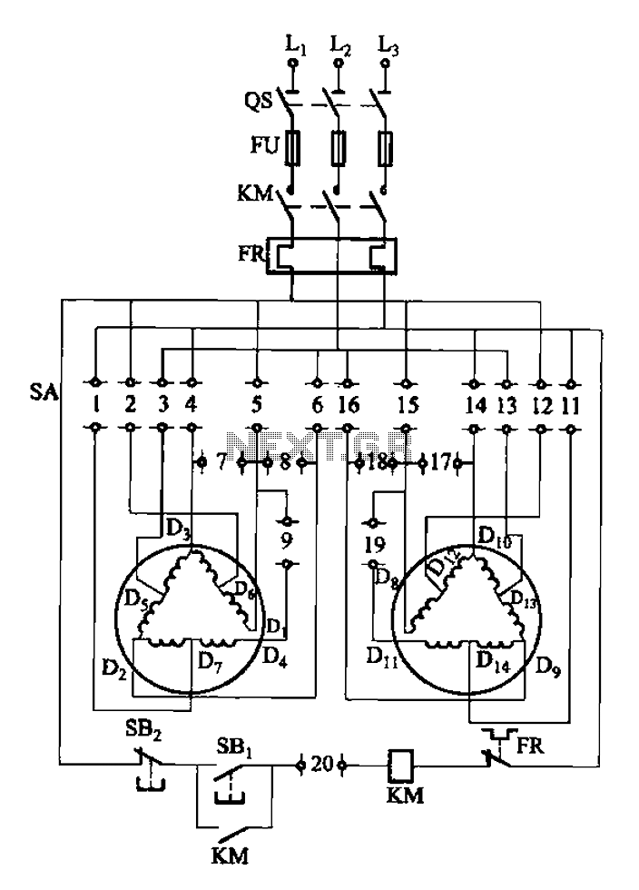
2Y-Y-2 - connection four-speed motor switch control circuit
3-119 circuit shown in FIG. By combining switch SA, realize stator windings, 2, Y and 2Y connection corresponding to the motor speed n1...
2Y-Y-2 - connection four-speed motor switch control circuit
3-119 circuit shown in FIG. By combining switch SA, realize stator windings, 2, Y and 2Y connection corresponding to the motor speed n1...
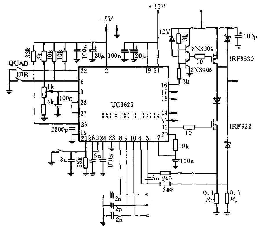
UC3625 brushless DC motor open loop speed control
28 is 45V/8A brushless DC motor driving circuit diagram. It is an open voltage-controlled, adjustable by one pin external potentiometer adjustment of the PWM du...
UC3625 brushless DC motor open loop speed control
28 is 45V/8A brushless DC motor driving circuit diagram. It is an open voltage-controlled, adjustable by one pin external potentiometer adjustment of the PWM du...
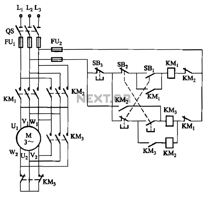
22kW and below hoist with Y- transfer power-saving circuit
22kW and below hoist with power-saving circuit Y- conversion circuit shown in Fig. The circuit on the basis of general hoist circuit adds a CJ20-10A exchange co...
22kW and below hoist with Y- transfer power-saving circuit
22kW and below hoist with power-saving circuit Y- conversion circuit shown in Fig. The circuit on the basis of general hoist circuit adds a CJ20-10A exchange co...
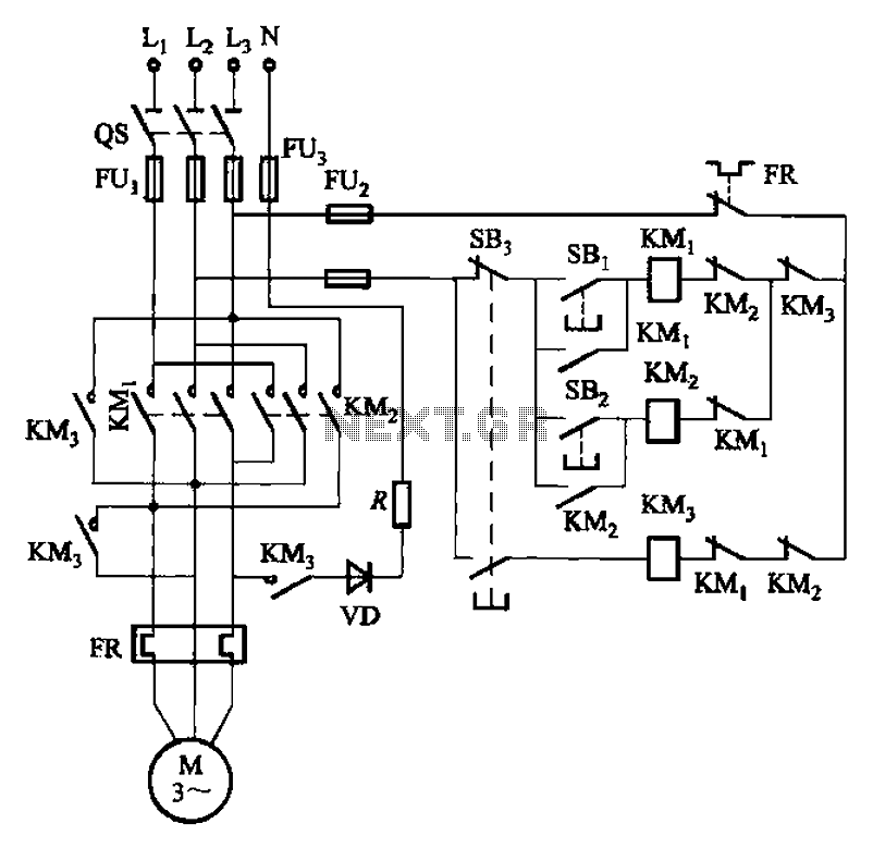
Forward and reverse operation of the dynamic braking circuit 2
1The circuit shown in Figure 3-145. The line uses a rectifier diode rectifier brake for neutral grounding of the three-phase four-wire power supply system. ...
Forward and reverse operation of the dynamic braking circuit 2
1The circuit shown in Figure 3-145. The line uses a rectifier diode rectifier brake for neutral grounding of the three-phase four-wire power supply system. ...
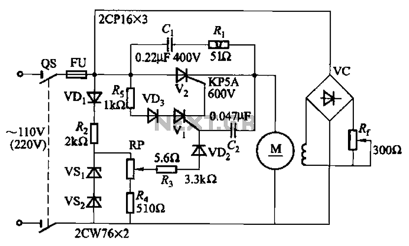
100W resistance triggered doer control circuit
100W resistance triggered doer control circuit It is dragging the arc welding machine control circuit of the most simple kind. Adjustment potentiometer Rr, can ...
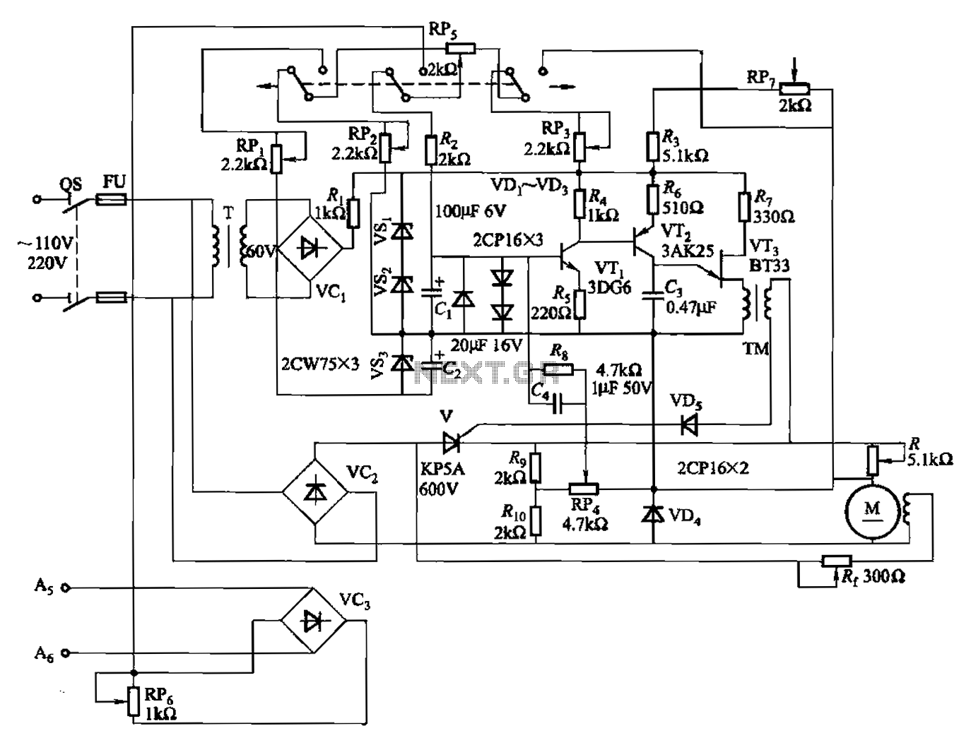
100W full-wave single-junction transistor trigger doer control circuit
100W full-wave single-junction transistor trigger doer control circuit It is suitable for constant or variable speed wire feed control wire feed motor. The inpu...
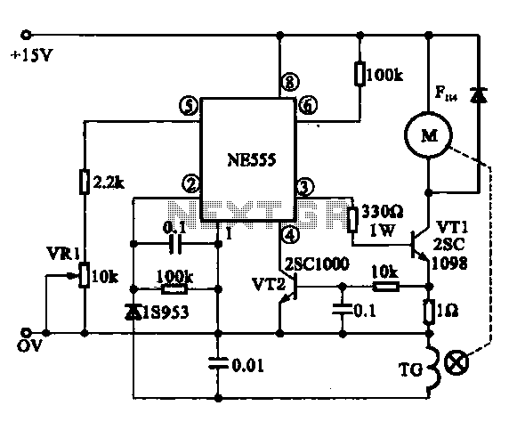
Miniature DC Motor Speed Control circuit
Miniature DC Motor Speed Control circuit b Having a steady speed function micro motor drive circuit steady speed Miniature DC motor control circuit shown in Fig...
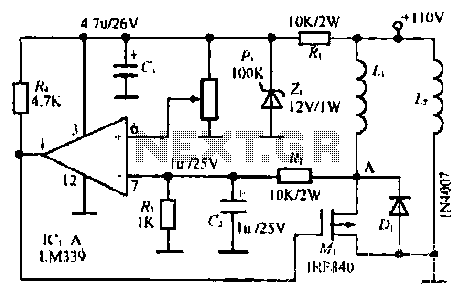
Stimulated simple motor speed control circuit
Ic, spread the use of electric comparator LM339c1 / 4), the potentiometer B to set the desired degree of construction, built-degree feedback signal by R., white...
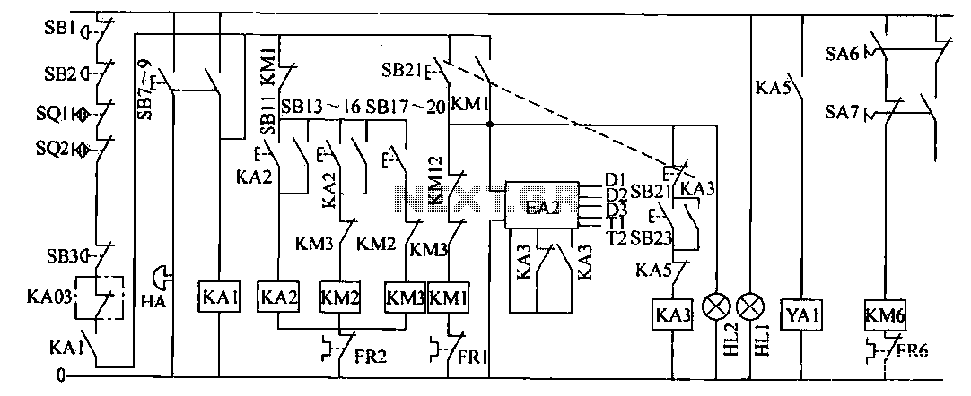
Color offset printing circuit
The operation control circuit mainly by the button switch SB21. Contactor KM1 composed contactor KM1 main contact directly control the operation of the main mot...

Motor Y starting circuit shape
Motor windings are scheduled to join Y Rong, while L IS ON, 2JC {}} electric suction, Union minister motor Y} i pick Save iIf /) f ~ tjj. ON 115 causes JMP - S ...
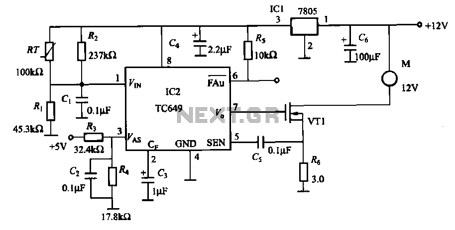
TC649 motor drive circuit with overheat protection
Motor is heating devices, by accident or overload often caused when the coil winding temperature is too high, as shown in FIG. 1-9 TC649 motor overheating prote...