


As current feedback circuit of four b
#current feedback
#three-phase rectifier
#current transformer
#rectifier circuit
#feedback circuit
#open delta
#current cutoff
#power electronics
#AC-DC conversion
#electrical engineering
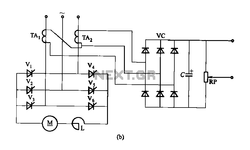
Description: Figure 16-40 illustrates a three-phase rectifier circuit featuring a current cutoff feedback mechanism. In part (a) of the figure, three current transformers are utilized, while part (b) shows the configuration using two current transformers connected in an open delta secondary arrangement.
The three-phase rectifier circuit depicted in Figure 16-40 is designed to convert alternating current (AC) from a three-phase supply into direct current (DC). The inclusion of a current cutoff feedback circuit enhances the protection and efficiency of the system by ensuring that the output current remains within safe operational limits.
In part (a), the use of three current transformers allows for precise monitoring of the current flowing through each phase of the rectifier. These transformers provide real-time feedback to the control system, enabling it to adjust the rectification process dynamically. This ensures that any imbalances in the current are detected and corrected promptly, which is critical for maintaining the reliability of the rectifier circuit.
In part (b), the configuration with two current transformers connected in an open delta secondary arrangement offers a more economical solution while still providing effective current monitoring. This setup reduces the number of components required, which can be advantageous in applications where space or budget constraints are a concern. The open delta arrangement allows for the measurement of phase currents while still providing adequate feedback for the control system to function effectively.
Overall, the design of the three-phase rectifier circuit with current cutoff feedback is essential for applications requiring stable and reliable DC power, particularly in industrial environments where three-phase systems are prevalent. The choice between using three individual current transformers versus a pair in an open delta configuration depends on the specific requirements of the application, including factors such as cost, space, and the level of precision needed in current monitoring.Figure 16-40 three-phase rectifier circuit current cutoff feedback circuit. Figure 16-40 (a) use three current transformers; Fig. 16 40 (b) using two connected in open delta se condary current transformer.
The three-phase rectifier circuit depicted in Figure 16-40 is designed to convert alternating current (AC) from a three-phase supply into direct current (DC). The inclusion of a current cutoff feedback circuit enhances the protection and efficiency of the system by ensuring that the output current remains within safe operational limits.
In part (a), the use of three current transformers allows for precise monitoring of the current flowing through each phase of the rectifier. These transformers provide real-time feedback to the control system, enabling it to adjust the rectification process dynamically. This ensures that any imbalances in the current are detected and corrected promptly, which is critical for maintaining the reliability of the rectifier circuit.
In part (b), the configuration with two current transformers connected in an open delta secondary arrangement offers a more economical solution while still providing effective current monitoring. This setup reduces the number of components required, which can be advantageous in applications where space or budget constraints are a concern. The open delta arrangement allows for the measurement of phase currents while still providing adequate feedback for the control system to function effectively.
Overall, the design of the three-phase rectifier circuit with current cutoff feedback is essential for applications requiring stable and reliable DC power, particularly in industrial environments where three-phase systems are prevalent. The choice between using three individual current transformers versus a pair in an open delta configuration depends on the specific requirements of the application, including factors such as cost, space, and the level of precision needed in current monitoring.Figure 16-40 three-phase rectifier circuit current cutoff feedback circuit. Figure 16-40 (a) use three current transformers; Fig. 16 40 (b) using two connected in open delta se condary current transformer.
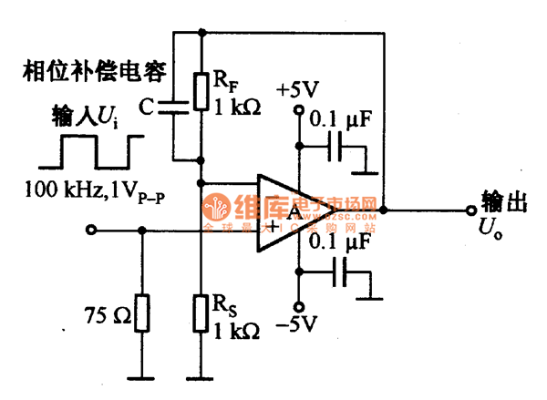
Feedback resistance circuit diagram of current feedback operational amplifier
The current feedback operational amplifier maintains a consistent bandwidth even when the open-loop gain is altered. This characteristic makes it particularly suitable for applications in video signal amplification and the driving circuits of video cables. The accompanying diagram illustrates a...
Feedback resistance circuit diagram of current feedback operational amplifier
The current feedback operational amplifier maintains a consistent bandwidth even when the open-loop gain is altered. This characteristic makes it particularly suitable for applications in video signal amplification and the driving circuits of video cables. The accompanying diagram illustrates a...
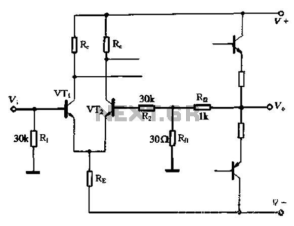
A feedback circuit and the differential input stage bias circuit is provided separately
The circuit utilizes the configuration illustrated in Figure 1-36, with the feedback circuit and bias circuit implemented separately. The feedback resistor, Rfl, is approximately 30 ohms. To maintain the desired amplification, the resistor R queue is set to 1 kilo-ohm...
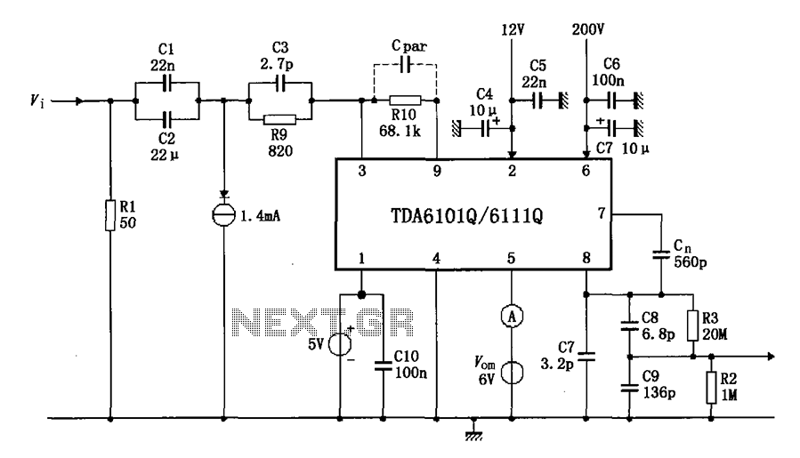
Test circuit diagram with feedback factor of 1 83 DA6101Q 6111Q
The test circuit features a feedback factor of 1/83 utilizing the DA6101Q/6111Q. The input signal is fed through a network comprising resistors R1 and R9, and capacitors C1, C2, and C3, entering the TDA6101Q, which includes three pins for the...
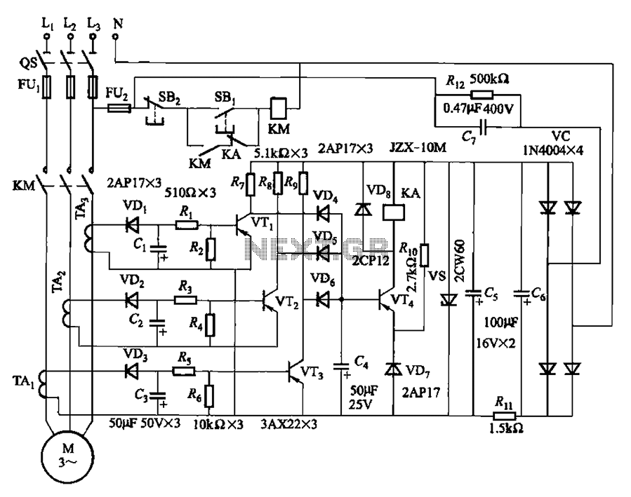
Detected line current Phase protective circuit 2
The current detection signal is obtained from three current transformers after rectification and filtering, resulting in three DC voltage outputs. These voltages are applied to transistors VT1, VT2, and VTa between the base and emitter. The signal is amplified by...
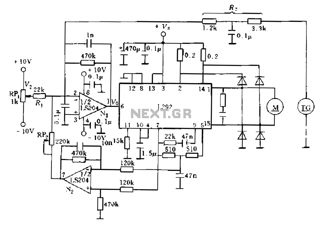
Having a current negative feedback speed control system
An alternative solution involves enhancing the existing feedback signal directed to an error amplifier summing junction, which is integrated into a current feedback loop for improvement. The L292 circuit demonstrates that the electrical current is proportional to the average current...
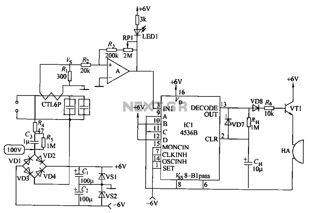
Computer AC power source monitoring circuit
The circuit principle involves using a current transformer for current sensing due to the large AC power load of computers. This setup detects whether there is current in the power line, enabling the determination of its status. The LM393 comparator...
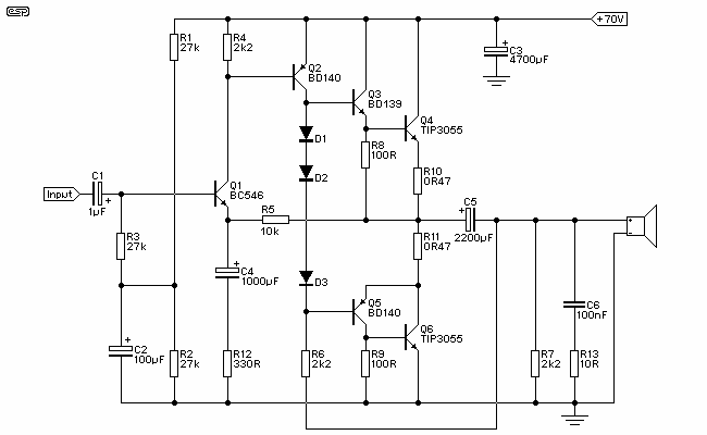
Simple Current Feedback Power Amplifier
Figure 1 shows the circuit. A major change from all of the designs from that era is the speaker coupling capacitor - 1000uF (for a -3dB of 20Hz and a 8 Ohm load) was the most common value. This is...