
pull up and pull down resistor
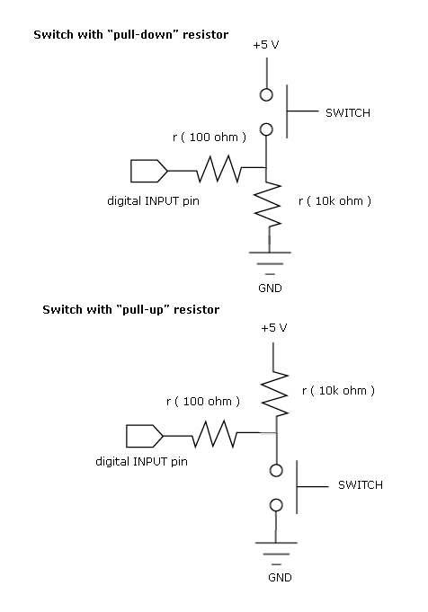
In digital electronics, understanding the behavior of floating inputs is crucial for reliable circuit operation. A floating input is one that is not connected to a definite voltage level, and it can pick up noise, leading to unpredictable states in digital logic devices. To avoid this, pull-up and pull-down resistors are employed.
In a pull-up resistor configuration, the resistor is connected between the input pin of the logic IC and the positive supply voltage (Vcc). This ensures that when the input is not actively driven low, it defaults to a high state (logic 1). Conversely, in a pull-down configuration, the resistor connects the input pin to ground, ensuring that the input defaults to a low state (logic 0) when not driven high.
The choice of resistor value is important for balancing power consumption and response speed. A 10 kΩ resistor is commonly used as it provides a good compromise between current draw and response time. Lower resistor values will result in higher current consumption, while higher values may lead to slower response times due to increased resistance to rapid voltage changes.
In summary, proper handling of floating inputs through the use of pull-up or pull-down resistors is essential in digital circuit design to ensure predictable behavior and efficient power management.Most of the beginners in digital electronics assume that the hanging input is a logic 0. Then, that`s a misconception. They are neutral state which can be a logic 0 or a logic 1. This will bring chaos on your circuit operation. As you can see, in each case there is a default input. For a pull-up, the default input to the logic IC is 1. And for the pull-down, the logic is 0. The resistor also provide a current limiting function thus affecting power consumption of the input section. 10kohms is the commonly value but any value can be use depending on your application. 🔗 External reference
Related Circuits
A 1997 Ford Thunderbird experienced a failure of the blower/fan when the air conditioning was activated, accompanied by a snapping sound under the instrument panel. This resulted in no airflow for the air conditioning, heater, or defrost functions. The...
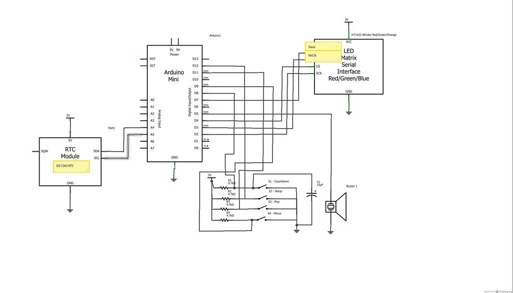
The device is designed to promote respectful time management during meetings, particularly useful in ship-room or SCRUM meetings. The following is a list of components required, including links for purchasing specific parts. It is advisable to check eBay or...
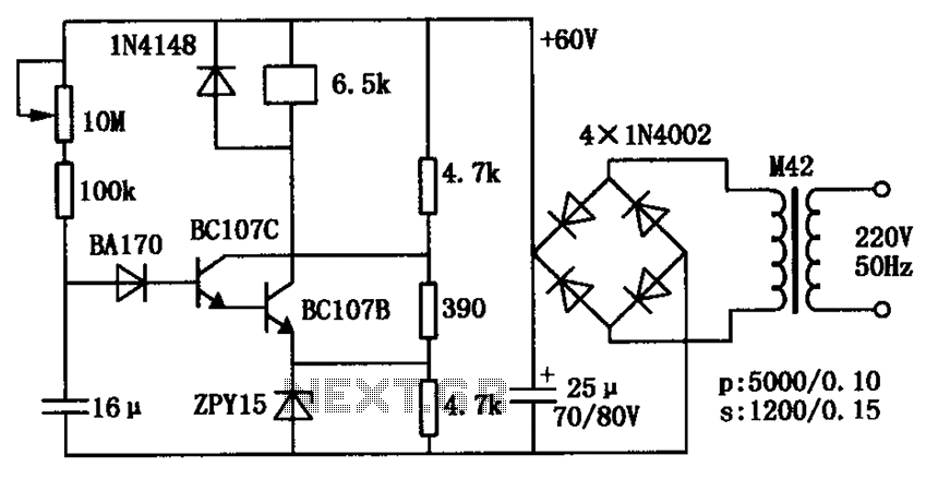
The circuit consists of a transistor relay delay pull mechanism. Initially, with a 16 µF capacitor at zero voltage, both transistors are off, and the relay remains inactive. As the 16 µF capacitor charges over time, the voltage increases...
The TPS6420x controller is designed to operate from one to three series-connected cells or from a 3.3 V or 5 V supply obtained from a USB port. At its output, it can produce 3.3 V at 2 A, suitable...
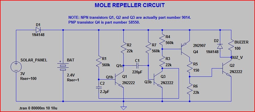
A healthy population of moles exists in the vicinity, prompting the purchase of four inexpensive ultrasonic mole deterrents from eBay to encourage them to relocate. The devices emit a frequency that is unpleasant to moles, leading them to vacate...
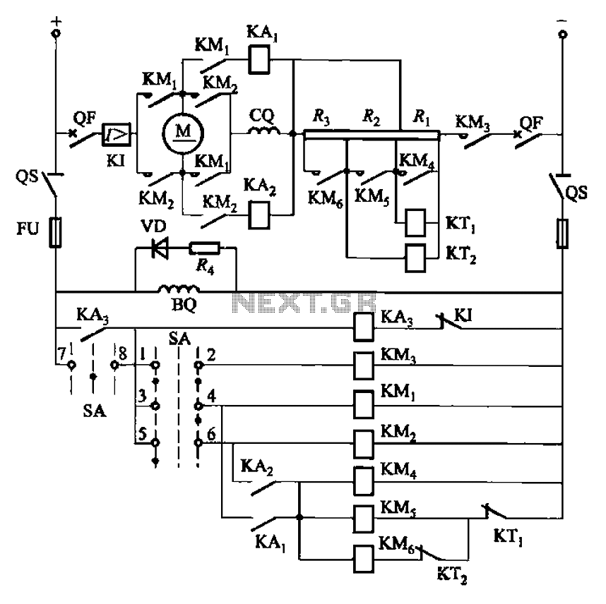
The circuit depicted in Figure 3-201 includes two starting resistors, with one controlled by a time relay. A master switch (SA) is utilized to manage the motor's reversing operation. The circuit incorporates a reverse braking mechanism, which is automatically...