
One of reversing circuit reverse braking resistor in series with a DC motor armature start

The circuit in question is designed to facilitate the controlled operation of DC motors, particularly in applications requiring both forward and reverse motion. It utilizes a combination of starting resistors to manage the initial current during motor startup, which is critical in preventing damage to the motor. The time relay adds an element of automation, allowing for a delay before the starting resistor is cut out of the circuit, thereby providing a smooth transition between starting and operational phases.
The reverse braking system is a pivotal feature of this circuit, allowing the motor to decelerate efficiently when reversing direction. The use of the reverse flow limiting resistor (Ri) is essential, as it prevents excessive reverse current that could potentially harm the motor or the overall circuit. The design ensures that during the braking phase, the circuit maintains control over the armature current, which is vital for the safe operation of the motor.
Contactor components (KMi, KM2, KM3, and KM4) play significant roles in directing the flow of electricity within the circuit. The forward and reverse contactors enable the motor to switch directions seamlessly, while the main circuit contactor ensures that the motor receives the appropriate power supply during operation. The inclusion of an overcurrent relay (KI) is a critical safety feature, providing protection against potential overloads and short circuits, which are common risks in motor operations.
Overall, this circuit exemplifies a robust design that addresses the complexities of motor control, emphasizing safety, efficiency, and versatility across different types of DC motor configurations. Circuit shown in Figure 3-201. The circuit has two starting resistor, starting resistor controlled by the time relay cut; SA by a master switch to control the motor reversing o peration; shut down, the use of reverse brake, reverse braking is based on motor size Speed automatic control. This circuit series-wound type, shunt and compound excitation type DC motors are applicable. Figure, Rz, Ra to start resistance; Ri is reverse flow limiting resistor, the braking process in reverse access armature circuit to limit the reverse current brake.
When the motor speed from zero to start reverse, Ri is short, does not affect the normal reverse L start the discharge resistor R4; KMi is forward contactor; KM2 to reverse contactors; KM3 main circuit (armature ) contactor; KM4 to reverse brake connector. Overcurrent relay KI for overload and short circuit protection.
Related Circuits
A high-quality tone burst generator can be constructed using a 556 Dual Timer. The first half of the timer can be configured as a one-shot, while the second half can function as an oscillator. The 556 Dual Timer is an...
A two-phase servo motor features a field winding and a control winding. When there is a 90° phase difference between the two, it generates rotational torque. A potentiometer connected to the motor shaft measures the voltage difference between the...
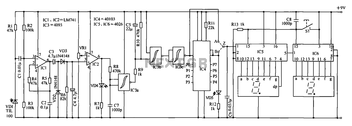
The device being constructed will serve as a metal detector, capable of locating metal objects such as coins, nails, and keys, including car keys that may be misplaced. It can also detect gold, although it may not possess industrial...
The digital counter circuit described utilizes an infrared signal to detect moving targets, making it suitable for counting small devices on a production line as they move along a conveyor belt. This circuit can also be employed for various...
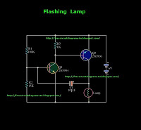
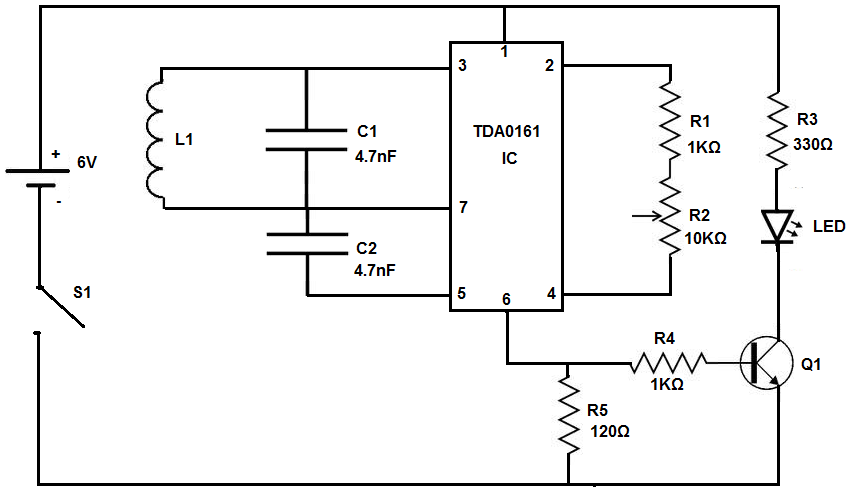
This is a flashing lamp circuit. This circuit operates with a 6V power supply. It can be installed on a bicycle or a car. A common transistor, the 2N3904, is used in this circuit. The flashing lamp circuit is designed...
The gain of the single-stage virtual earth amplifier IC1 is determined by the drain-source resistance of the field-effect transistor (FET). Resistors R1, R2, and R3 linearize the FET's voltage-current characteristic. A control voltage is derived from the output signal...