
Length 1 minute delay relay pull transistor circuit diagram
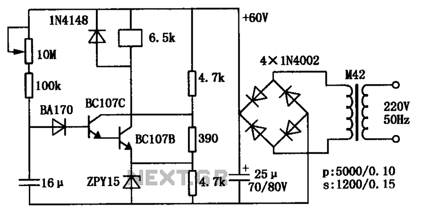
The described circuit employs a transistor-based relay delay mechanism, which is useful in applications requiring a timed activation of a relay. The circuit begins in a dormant state, with the 16 µF capacitor initially uncharged, resulting in both transistors being in the off state. This lack of current flow prevents the relay from engaging.
As the circuit is powered, the capacitor begins to charge through the connected resistive elements. The charging rate is influenced by the resistor values in the circuit, particularly the 10 MΩ resistor, which serves as a timing element. By altering this resistor's value, the delay time before the relay is activated can be fine-tuned, allowing for versatility in timing applications.
Once the voltage across the capacitor reaches a predetermined threshold, both transistors are triggered into the on state. This action allows current to flow through the relay coil, thus engaging the relay. The relay's activation can be used to control larger loads or other circuits, making this a practical solution for various electronic applications where delayed activation is necessary.
The maximum delay of 60 seconds is significant for applications that require a prolonged waiting period before activation, such as in timing circuits, automation systems, or safety interlocks. The simplicity of the circuit design, combined with the adjustable delay feature, makes it an effective solution for creating controlled timing sequences in electronic systems. Proper selection of the capacitor and resistor values is crucial for achieving the desired operational characteristics. As shown is composed of a transistor relay delay pull circuit. Just power, 16 F capacitor voltage is zero, two transistors are off, the relay does not operate. With 16 F capaci tor charge, over a period of time to which the voltage reaches a high level, two transistors are turned on, the relay delay pull. The delay time of up to 60s. Delay time can be adjusted by 10M resistor.
Related Circuits
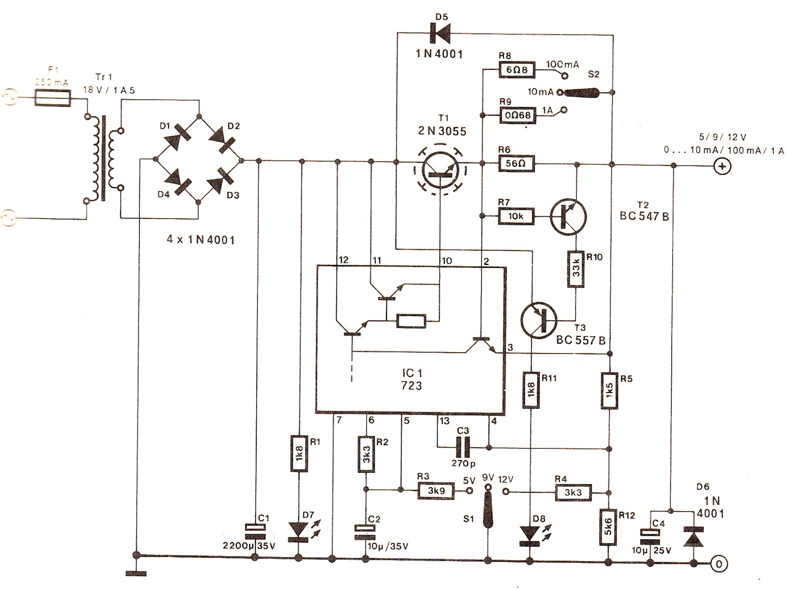
The output voltage can be increased easily by placing a resistor in parallel with Ra until it reaches precisely 5.0 V. Switches S1 and S2 are preferably SPDT types with a center position, but three-way rotary switches can also...

This is an infrared-based broken beam alarm designed to protect doors and entry passages. It emits a loud alarm when someone crosses the invisible infrared barrier. The infrared-based broken beam alarm system operates by utilizing a pair of infrared emitters...

The hardware design for USB is quite minimal, which is advantageous. However, it quickly becomes apparent that the simplicity of the hardware design leads to complex communication and control software, which will be explored further in the theory and...
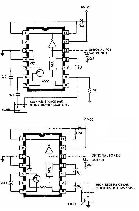
This electronic liquid detector circuit diagram is based on the ULN2429 monolithic bipolar integrated circuit designed for detecting the absence or presence of many different types of liquids. The ULN2429 electronic liquid detector circuit can be used in automotive,...
The i-TRIXX circuit is designed to prevent issues for individuals traveling in a caravan. It provides an early warning system through an illuminated LED, alerting users when the battery charge is low, thereby preventing the inconvenience of being unable...
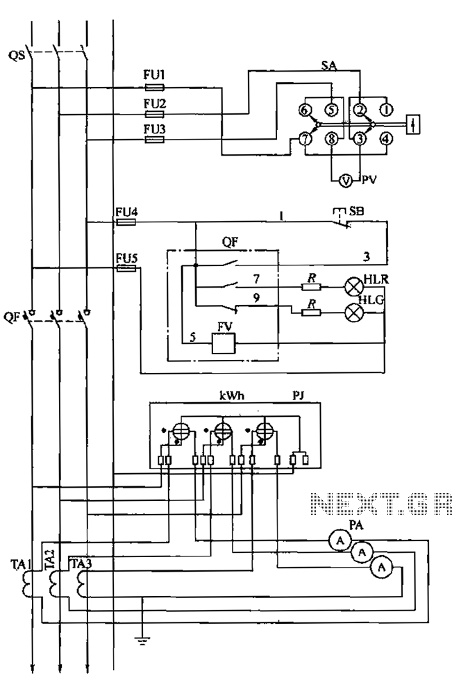
The BSL is illustrated in a low-voltage distribution panel wiring diagram. It consists of three main components: the voltage measuring circuit, secondary circuit protection, and the energy metering circuit. (1) The voltage measuring circuit includes a voltage switch (SA)...