


VCR Robot
#VCR parts
#Nemesis microcontroller
#PIC 16F88
#DIY robot
#Kronos Robotics
#simple robot
#bootloader
#import taxes
#minimal components
#hobby robotics
Description: A sample robot was constructed using components from VCRs, with only the minimum necessary parts to create the simplest robot concept. Initially, the Nemesis microcontroller, produced by Kronos Robotics, was employed; however, it was not an optimal choice for Romania due to high import taxes that nearly doubled its price. The Nemesis is based on the PIC 16F88 and comes with a pre-programmed bootloader. This feature enables programming via a serial port on a PC with a logic level adapter. Kronos Robotics also offers Athena, a free Basic compiler, extensive sample code, and excellent support, making it an ideal choice for beginners as Basic is easier for young individuals to learn. The Nemesis is priced at $12.95. In contrast, the PIC 16F88 costs around $3 but requires a programmer, which is the cheapest at $40, and the PBasic compiler is priced at $99, making it too expensive. An alternative suggested is using an AVR ATtiny26 with Bascom-AVR for programming, reducing the total project cost to approximately $15. The required components for this project include the Nemesis microcontroller, the SN754410 motor driver IC, a prototyping board, the LM2940 voltage regulator, a battery box, 18-pin and 16-pin DIP sockets, a 5-pin female socket, and a strip of breakable male pins. Additionally, a serial level shifter was purchased from the Kronos Robotics website to program the microcontroller. Most other components can be salvaged from two VCRs to obtain two identical motors. Other miscellaneous items needed include cable ties, construction nails, wire, small wood screws, and four AA batteries. The primary component (IC1) is the Nemesis microcontroller, which serves as the robot's brain. It features 15 general I/O pins, with seven connected to the internal Analog to Digital converter, two connected to the built-in UART (serial) interface, and a Reset pin (Attn). Operating at 8 MHz, it has 1024 bytes of memory for user programs and includes a timer that can generate a PWM signal on pin 6. The second component (IC2) is the SN754410E Quad Half H-Bridge, functioning as the motor driver. This IC can drive two DC motors or one stepper motor, providing up to 1 amp of current per motor (or winding). It includes two Direction pins and an Enable pin for each motor. When the Enable pin is set high, the motors receive power; otherwise, they can spin freely. If pin A is high (1) and pin B is low (0), the motor rotates clockwise; if pin A is low and B is high, the motor rotates counterclockwise. If both pins are high or low, the motor is braked, short-circuiting the output pins connected to the motors. When power is cut while the motor is spinning, it acts as a generator, causing the generated current to return to the motor, which slows it down rapidly and resists further spinning after coming to a complete stop. This H-bridge IC includes internal clamp diodes to protect the circuit from back-generated currents. The IC is powered by a regulated 5V supply, while the motors are powered directly from the battery, allowing them to receive higher voltages and currents than the rest of the circuit. The U1 component is a PNA4613 Photo IC, an infrared photo transistor equipped with an internal filter that permits only 40 kHz modulated signals to pass through. It has an internal pull-up resistor, ensuring that the output pin remains high in the absence of a signal. This IC is commonly found in TVs and VCRs as a remote IR signal receiver. It can be utilized to remotely control the robot using a Sony TV remote or as a proximity sensor to detect objects in the robot's path from a certain distance, in conjunction with two IR LEDs (IRLED-LEFT and IRLED-RIGHT) positioned beside U1. The proximity sensor operates by having the microcontroller generate a 40 kHz PWM pulse to one of the LEDs for a brief period, after which it turns off and checks the sensor at pin 5. If an object is detected in front of the LED, some of the infrared light is reflected back to the sensor, indicating the presence of an obstacle.A sample robot, using parts from VCRs and bought only the minimum necessary to make the simplest robot I could think of. At the time I was using the Nemesis microcontroller, produced by Kronos Robotics, however this was not a good choice for Romania, because import taxes would have made their price almost double.
Nemesis is a PIC 16F88 with a pre-programmed bootloader. This feature allows the user to program it from the serial port of the PC through a logic level adapter. Kronos Robotics also provides Athena, a free Basic compiler, lots of sample code and great support. Basic is easier to learn by young people, so I thought it is a good choice for beginners. And Nemesis costs only $12. 95. A PIC 16F88 costs about $3, but needs a programmer (the cheapest I could find is $40) and the PBasic compiler costs $99.
Too expensive. Now I would use an AVR ATtiny26 and Bascom-AVR for programming, cutting the price to about $15 for the whole project. The only parts you will need to buy for this project are the Nemesis microcontroller, the SN754410 motor driver IC, a prototyping board, the LM2940 voltage regulator, a battery box, 18 pin and 16 pin DIP sockets, a 5 pin female socket, a strip of breakable male pins.
I also bought a serial lever shifter to program the microcontroller from Kronos Robotics website. All the other parts you can get from a VCR, but you will need 2 VCRs to get 2 identical motors. You will also need a few cable ties, a couple construction nails, wire, a couple small wood screws and 4 AA batteries. The main part (IC1)is the Nemesis microcontroller, the robot`s brain. As you can see, it has 15 general I/O pins, 7 of which are connected to the internal Analog to Digital converter and 2 are connected to the built in UART (serial) interface and a Reset pin (Attn).
It runs at 8MHz and it has 1024 bytes of memory for user programs. It also has a timer that can be used to generate PWM signal on pin 6. IC2 part is the SN754410E Quad Half H-Bridge, which is the motor driver. This IC can drive 2 DC motors or one step by step motor. It provides currents of up to 1 amp per motor (or winding). The IC has 2 Direction pins and an Enable pin for each motor. If the Enable pin is set to high, the motors are powered, otherwise they can spin freely. If pin A is high (1) and pin B is low (0), the motor spins clockwise, if the pin A is low and B is high, the motor spins counterclockwise. If both pins are either high or low, the motor is braked (the output pins connected to the motors are short-circuited - if the power is cut when the motor is spinning, the motor becomes a generator, but the generated current will go back to the motor and make the motor spin in the opposite direction, slowing it down fast and after a complete stop, it makes the motor resist spinning).
This H bridge IC has internal clamp diodes to protect the circuit from the back generated currents. The IC is powered from regulated 5V but motors are powered directly from the battery. This way they can get bigger voltages and current than the rest of the circuit. The U1 part is a PNA4613 Photo IC. This IC is an infra red photo transistor with an internal filter that allows only 40 kHz modulatedsignal to pass. It has an internal pull up resistor, so in the absence of a signal the output pin is always high. This IC is regularly found in TVs and VCRs as the remote IR signal receiver. We can use this IC to remote control the robot using a Sony TV remote, or as a proximity sensor, to detect objects in the robot`s path from a certain distance, together with the 2 IR LEDs (IRLED-LEFT and IRLED-RIGHT) flanking U1.
The proximity sensor works like this: the microcontroller generates a 40 kHz PWM pulse one of the LEDs for a short time, then it turns is off and checks the sensor pin 5. If there is an object in front of the LED, some of th
Nemesis is a PIC 16F88 with a pre-programmed bootloader. This feature allows the user to program it from the serial port of the PC through a logic level adapter. Kronos Robotics also provides Athena, a free Basic compiler, lots of sample code and great support. Basic is easier to learn by young people, so I thought it is a good choice for beginners. And Nemesis costs only $12. 95. A PIC 16F88 costs about $3, but needs a programmer (the cheapest I could find is $40) and the PBasic compiler costs $99.
Too expensive. Now I would use an AVR ATtiny26 and Bascom-AVR for programming, cutting the price to about $15 for the whole project. The only parts you will need to buy for this project are the Nemesis microcontroller, the SN754410 motor driver IC, a prototyping board, the LM2940 voltage regulator, a battery box, 18 pin and 16 pin DIP sockets, a 5 pin female socket, a strip of breakable male pins.
I also bought a serial lever shifter to program the microcontroller from Kronos Robotics website. All the other parts you can get from a VCR, but you will need 2 VCRs to get 2 identical motors. You will also need a few cable ties, a couple construction nails, wire, a couple small wood screws and 4 AA batteries. The main part (IC1)is the Nemesis microcontroller, the robot`s brain. As you can see, it has 15 general I/O pins, 7 of which are connected to the internal Analog to Digital converter and 2 are connected to the built in UART (serial) interface and a Reset pin (Attn).
It runs at 8MHz and it has 1024 bytes of memory for user programs. It also has a timer that can be used to generate PWM signal on pin 6. IC2 part is the SN754410E Quad Half H-Bridge, which is the motor driver. This IC can drive 2 DC motors or one step by step motor. It provides currents of up to 1 amp per motor (or winding). The IC has 2 Direction pins and an Enable pin for each motor. If the Enable pin is set to high, the motors are powered, otherwise they can spin freely. If pin A is high (1) and pin B is low (0), the motor spins clockwise, if the pin A is low and B is high, the motor spins counterclockwise. If both pins are either high or low, the motor is braked (the output pins connected to the motors are short-circuited - if the power is cut when the motor is spinning, the motor becomes a generator, but the generated current will go back to the motor and make the motor spin in the opposite direction, slowing it down fast and after a complete stop, it makes the motor resist spinning).
This H bridge IC has internal clamp diodes to protect the circuit from the back generated currents. The IC is powered from regulated 5V but motors are powered directly from the battery. This way they can get bigger voltages and current than the rest of the circuit. The U1 part is a PNA4613 Photo IC. This IC is an infra red photo transistor with an internal filter that allows only 40 kHz modulatedsignal to pass. It has an internal pull up resistor, so in the absence of a signal the output pin is always high. This IC is regularly found in TVs and VCRs as the remote IR signal receiver. We can use this IC to remote control the robot using a Sony TV remote, or as a proximity sensor, to detect objects in the robot`s path from a certain distance, together with the 2 IR LEDs (IRLED-LEFT and IRLED-RIGHT) flanking U1.
The proximity sensor works like this: the microcontroller generates a 40 kHz PWM pulse one of the LEDs for a short time, then it turns is off and checks the sensor pin 5. If there is an object in front of the LED, some of th
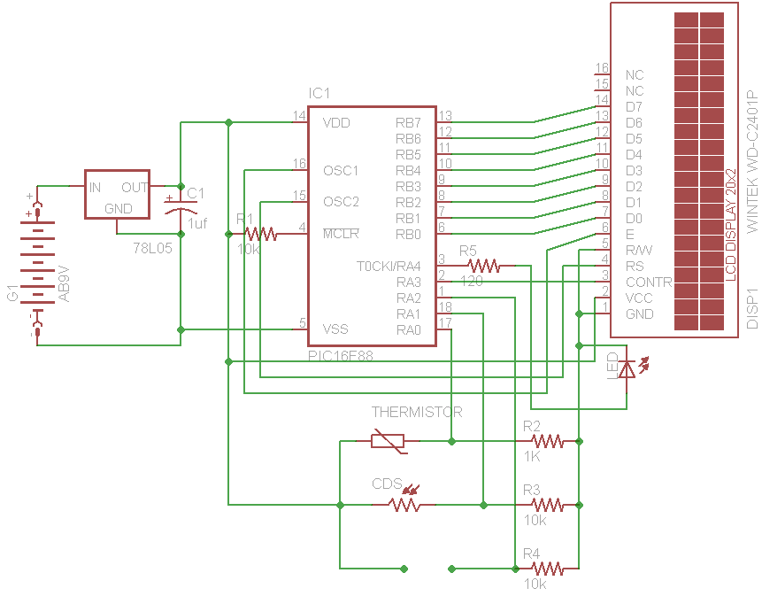
PIC 16F88 Digital Thermometer Light Meter and resistance ohm meter
The initial concept for this project involves interfacing the WINTEK WD-C2401P LCD panel with a PIC microcontroller. The intention is to incorporate several ADC readings to provide useful information on the LCD. PORTB on the PIC serves as the data...
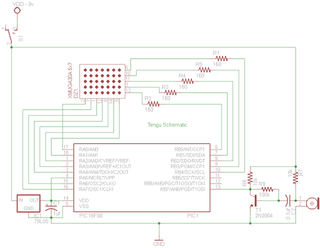
PIC 16F88 Microcontroller PIC based Tengu
Tengu derives its name from a mythical Japanese creature known for getting into mischief. However, this Tengu is more earthly in nature. It responds to voice and sounds, changing its facial features depending on the intensity of the sound. If...