
schematic computer multiplier sequence
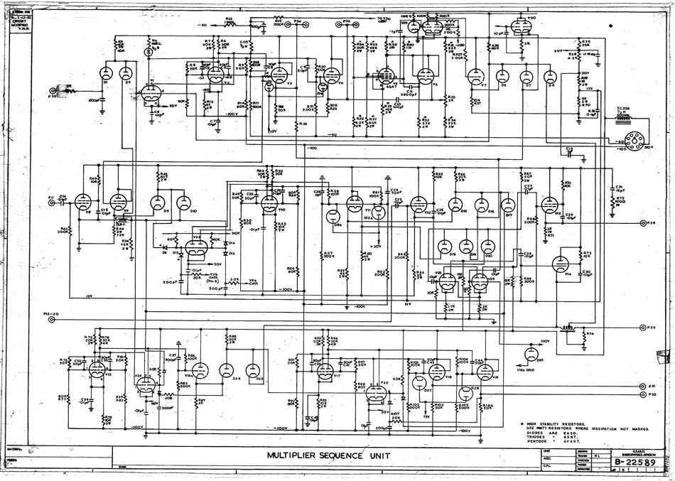
The schematic diagram of CSIRAC serves as a crucial reference for understanding the architecture and functionality of this pioneering computer. It provides a visual representation of the circuit, detailing how various components such as vacuum tubes, resistors, capacitors, and other elements are interconnected. Vacuum tubes, which function as electronic switches or amplifiers, were fundamental to the operation of CSIRAC, allowing for signal modulation and control.
Capacitors in the circuit played a vital role in energy storage and signal smoothing, contributing to the overall stability and performance of the computer. The schematic not only aids in the construction of the circuit but also facilitates troubleshooting and maintenance, enabling engineers to identify and rectify issues that may arise during operation.
Furthermore, the detailed connections illustrated in the schematic are essential for understanding the flow of electrical signals within the system. Each line and symbol represents specific electrical pathways and component functions, ensuring that the circuit operates as intended. This document is invaluable for both historical reference and educational purposes, providing insight into the early development of computing technology.Schematic diagram in hard copy relating to the computer CSIRAC. A schematic diagram shows the detailed connections between all the components in a circuit. Such diagrams were used to build circuits and later for testing. For CSIRAC, the most common components were vacuum tubes (valves), capacitors a.. 🔗 External reference
Related Circuits
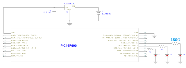
Below is the schematic integrated with the voltage regulator from the previous post. The PIC16F690 serves as the central controller of the system. This microcontroller is a mid-range option for hobbyists, offering more functionality than utilized in this project....
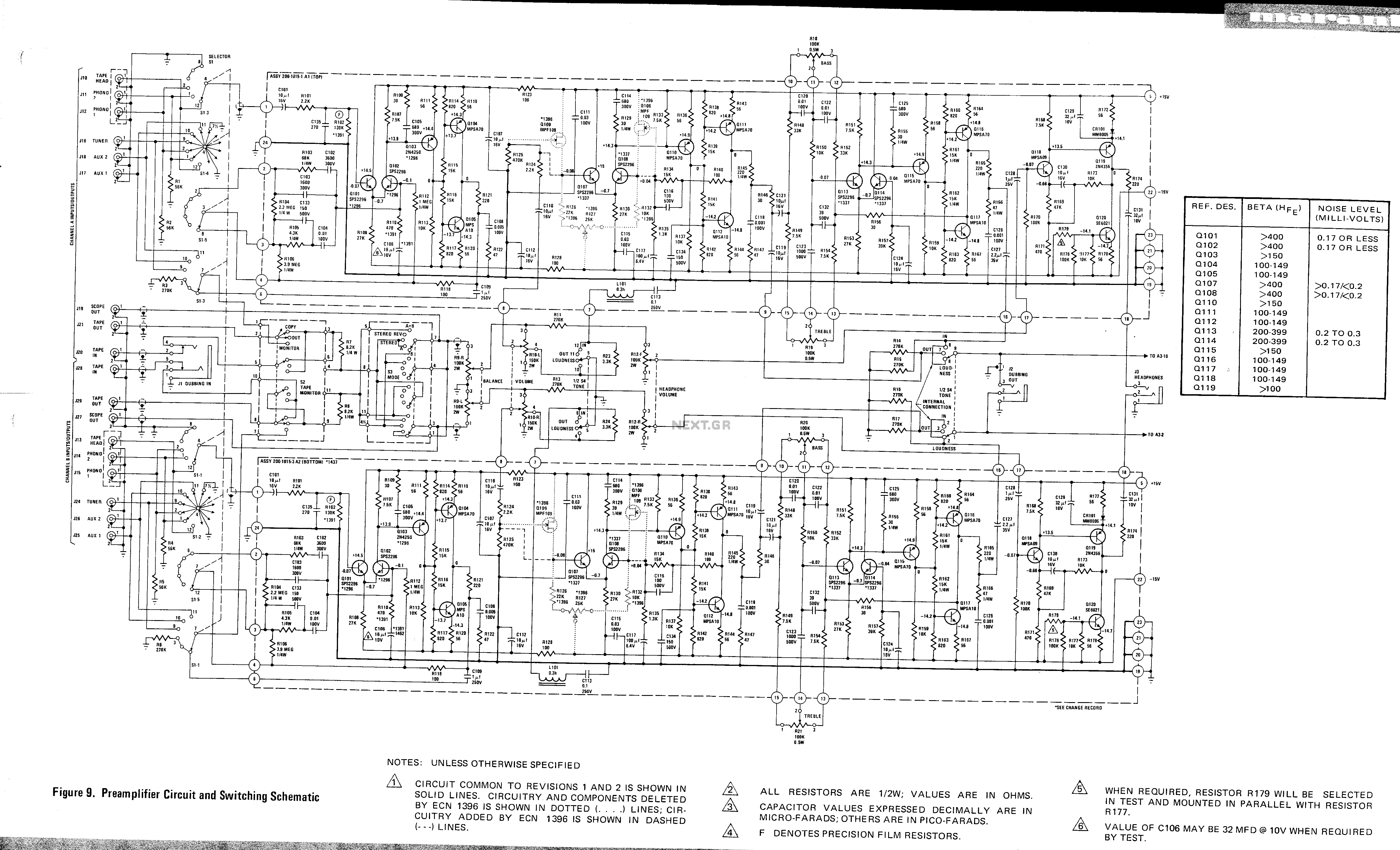
This is a preamplifier circuit and switching schematic for the Marantz Model 33. The Marantz Model 33 preamplifier circuit is designed to amplify low-level audio signals from various sources before sending them to a power amplifier. The schematic typically includes...

An interesting hobby circuit of a crank doorbell. The circuit is built around a 555 timer and a musical piezo buzzer. It operates using a 9-volt battery supply; a single 9-volt PP3/6F22 compact battery is sufficient to power the...
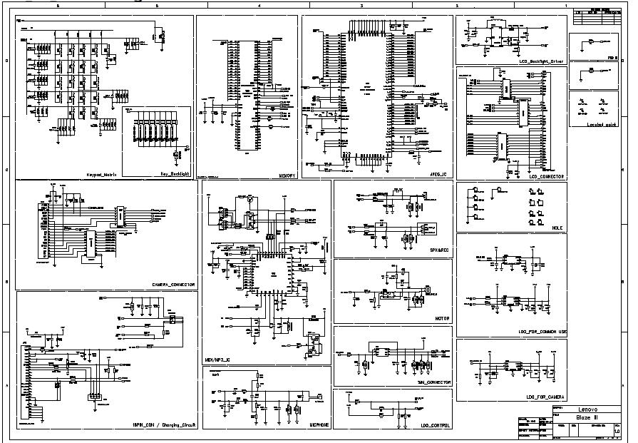
General use camera backlighting baseband circuit: the circuit includes a table of contents, Calyso, iota, matrix, keypad key, memory, IC image, LCD connector, LCD backlight driver, locate points, holes, Speaker4, camera connector, motor, MIDI/MP3 ICs, charging circuit, microphone phone,...
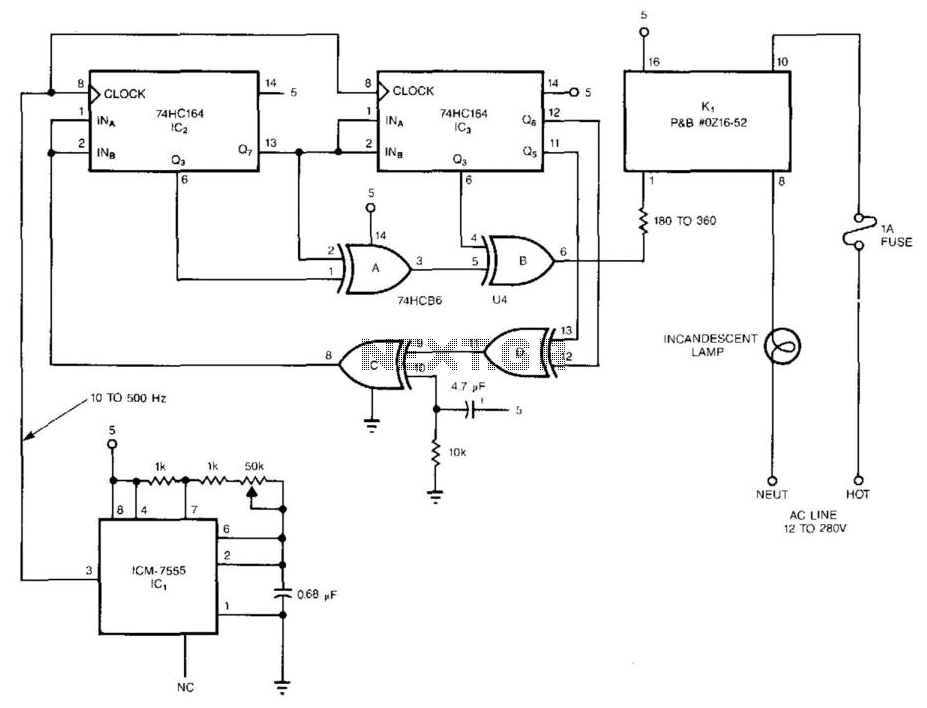
The pseudorandom sequencer drives a solid-state relay. When a low-wattage lamp is powered from the relay, the lamp will flicker like a candle's flame in the wind. Using higher-wattage lamps allows for the simulation of a fireplace or campfire...
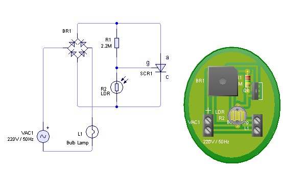
Adjust the value of R1 to achieve optimal performance of the LDR sensor. If, in practice, a resistance of 2.2 MΩ still activates the lamp, it is possible to increase the value of R1 to a larger resistance of...