
Marantz Model 33 Preamplifier circuit and switching schematic
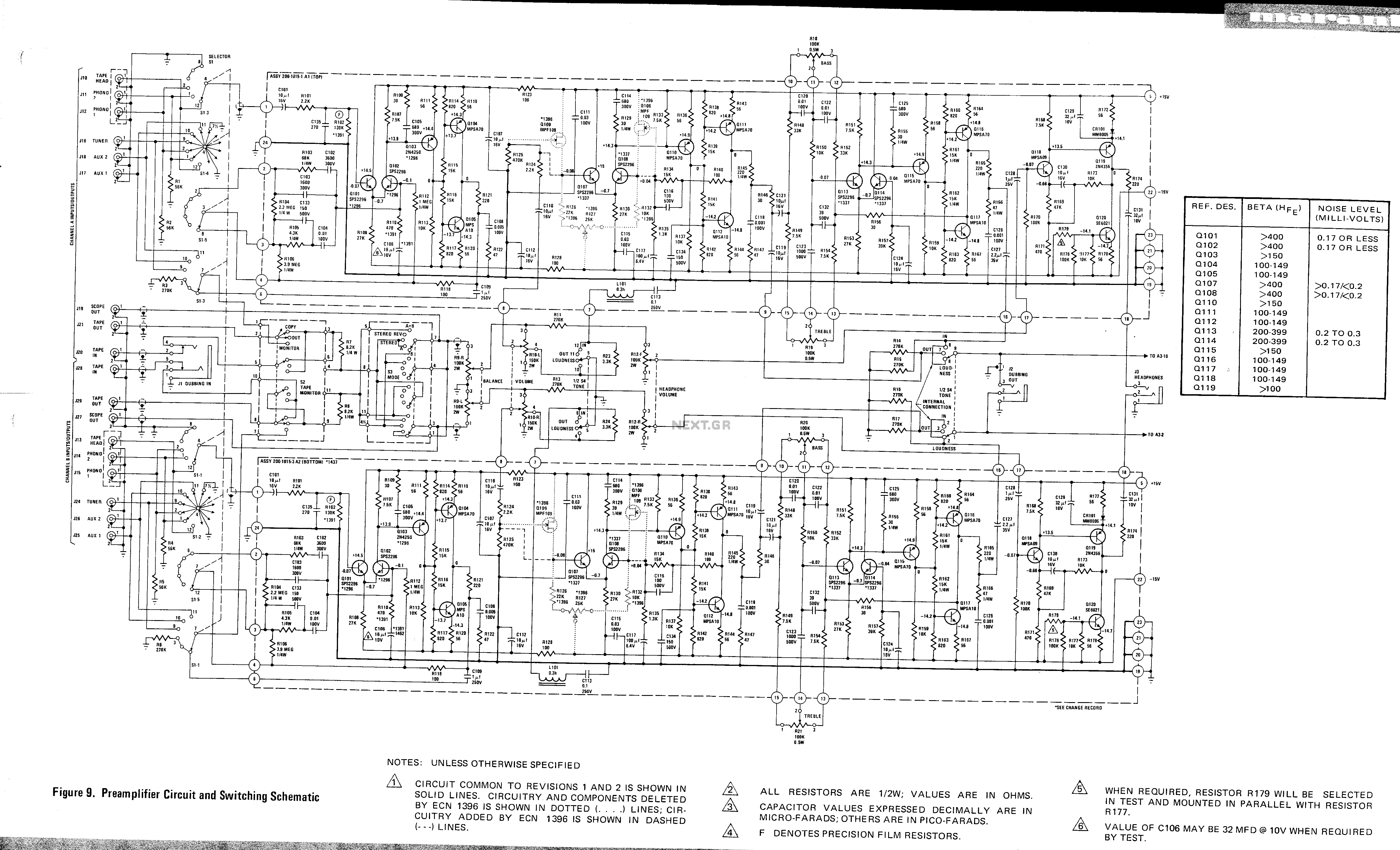
The Marantz Model 33 preamplifier circuit is designed to amplify low-level audio signals from various sources before sending them to a power amplifier. The schematic typically includes several key components such as operational amplifiers, resistors, capacitors, and switches to facilitate signal routing and gain control.
The circuit begins with input connectors that receive audio signals from sources like turntables, CD players, or other audio devices. From there, the signals pass through a series of capacitors that block any DC offset while allowing AC audio signals to pass. This is crucial for protecting downstream components from potential damage caused by DC voltages.
Operational amplifiers (op-amps) are central to the amplification process. They are configured in a non-inverting or inverting arrangement, depending on the desired gain characteristics. Feedback resistors are employed to set the gain of the op-amps, ensuring that the output signal is appropriately amplified without distortion.
Switching elements, such as toggle or rotary switches, are included in the schematic to allow users to select between different input sources. These switches may also provide options for adjusting the tonal quality of the audio signal, such as bass and treble controls.
Output capacitors are used to couple the amplified signal to the power amplifier while blocking any DC components. This ensures that only the amplified AC audio signal is transmitted to the next stage in the audio chain.
Overall, the preamplifier circuit for the Marantz Model 33 is engineered to provide high fidelity audio performance, characterized by low noise and minimal distortion, making it suitable for audiophiles and music enthusiasts. Proper layout considerations in the PCB design, including grounding and shielding, are essential to maintain signal integrity and minimize interference from external sources.This is a Preamplifier circuit and switching schematic for Marantz Model 33. 🔗 External reference
Related Circuits
This 300W RF power amplifier for an FM transmitter utilizes 2 x TP9383 transistors. It operates within the 88 - 108 MHz frequency band. The 300W RF power amplifier is designed specifically for FM transmission applications, providing high power output...
A buzzer circuit utilizes a PIC microcontroller to drive a piezo buzzer. The microcontroller is a low-power processor that is ideal for portable and compact devices where battery conservation is essential. The buzzer circuit employs a PIC microcontroller, which serves...
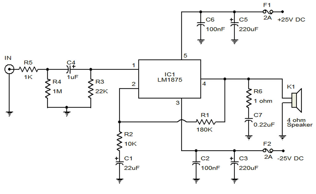
The circuit illustrates a 20-Watt audio amplifier diagram based on the LM1875 integrated circuit (IC). It is designed for use in automotive applications and provides an output power of 20 Watts. The 20-Watt audio amplifier circuit utilizing the LM1875 IC...
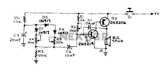
When the door is pushed, a whisper is heard that transitions to a higher frequency. The oscillator frequency is determined by the audio frequency coupling capacitance, C1, and the resistance connected between the base of transistor Q1 and ground....
This project involves a ding-dong doorbell circuit utilizing the 555 Integrated Circuit (IC). In a previous article, a simple doorbell circuit using the UM66 IC, a CMOS three-terminal melody IC, was discussed. The current circuit employs the NE555 IC...
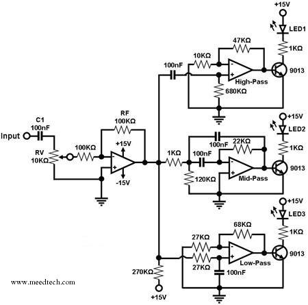
A simple circuit for converting an audio signal (such as one that comes from the output terminals of a CD player). The circuit basically consists of a buffer/amplifier stage and three filter circuits: a high-pass filter, a mid-pass filter,...