
halloween build part 3 full schematic
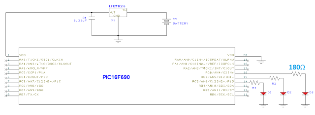
The schematic incorporates a PIC16F690 microcontroller, which operates as the central processing unit for the LED flashing system. The microcontroller is powered through a voltage regulator, ensuring stable operation across varying input voltages. The unused pins suggest that the design could be optimized by selecting a microcontroller with fewer pins, such as the ATTiny10 or a smaller Microchip variant, to reduce physical space and complexity.
The programming interface utilizes a PICKit 2, allowing for in-circuit programming via a dedicated header. This header is crucial for reprogramming the microcontroller without removing it from the circuit board. The inclusion of a small signal diode in place of the 47kΩ resistor provides flexibility in component selection, making the design adaptable to different assembly requirements.
The software logic operates primarily through a delay function, which is critical in generating the desired flashing patterns for the LEDs. The configuration of PORTC as output pins is essential, as it allows the microcontroller to control the state of the LEDs. Each LED is connected through a current-limiting resistor, calculated to ensure the LEDs operate within their specified current ratings. This ensures longevity and optimal performance of the LEDs while preventing damage due to overcurrent.
For accurate resistor selection, it is advisable to use Ohm's law and consult online calculators, which can simplify the process of determining the correct resistor values based on the LED specifications and desired brightness levels. The project's simplicity, while functional, highlights opportunities for enhancements, such as implementing more sophisticated control algorithms or integrating sensors for dynamic light control based on environmental stimuli. The upcoming posts will delve into the intricacies of the circuit board design and provide a comprehensive bill of materials, facilitating replication and further experimentation by hobbyists and engineers alike.Below you can see the rest of the schematic integrated with the voltage regulator from my last post. As I explained previously, the PIC16F690 is the brains of my system. This PIC is a mid-range option for hobbyists and has much more functionality than I made use of in this project. I originally thought I would make better use of it when I was in t he planning stages but everyone who has been following me knows how things turned out. You can see in the schematic I left 15 of the 20 pins open, which is a colossal waste of space. A better controller to use would have been the ATTiny10 from Atmel or a 6 pin micro from Microchip. Even the 16F84 that I had lying around could have saved some space and provided the same functionality (flashing an LED). I was able to program the chip using an in-circuit configuration with a PICKit 2 and could have included programming headers in the design if I intended to reprogram these devices in the future.
I have included another schematic of the in-circuit setup I used for the programming. You can substitute a small signal diode for the 47kohm resistor if that is handier for you. From what I can gather this setup is pretty standard across different families of microcontrollers and you can integrate this header into your printed circuit board design for on-the-fly reprogramming. You just have to make sure that the circuit isn`t operating while you are trying to program it and that no power is supplied to the programming pins when you do want to test the circuit.
This is less of a problem if you don`t have anything else connected to pin RA3 (configuration specific). The software is brain dead simple and written in C using the MPLABX IDE from Microchip (GUI pictured below).
All it does is call a delay function by passing an integer to represent the number of cycles through a 100ms countdown. I varied the timing for this function with each different pumpkin to create different patterns. The code I have uploaded to this post is based on a 20Hz flasher to create a strobe effect. I have linked a zip file to this post with all the necessary header files if you want to play around with lighting up some LEDs yourself.
You can download it here. If you look at the datasheet for the 16F690, you will see that PORTC corresponds to the RC0, RC1, RC2, and RC3 pins on the chip so you must first configure PORTC as outputs before running the main piece of the code. By setting these pins high in software, you place the chip`s supply voltage on the pins in question (RC0-RC3) and start to source current to whatever loads the pins are tied to.
In my case, they are all tied to LEDs with current limiting resistors. I have assumed Red LEDs in the schematic so different resistor values are necessary for other colors/source voltage combinations. I wanted to drive the LEDs at around 15mA so I used ohms law to determine the correct resistor based on the turn on voltage of the LEDs.
You can find online resistor calculators that will tell you what resistor to use based on your LED color and the current you desire. Otherwise, look up the forward drive current calculation for a diode. That`s about all I have to say concerning this design. It is easy to see why this project doesn`t amount to much more than a glorified LED flasher. Some obvious improvements are software upgrades to lengthen battery life, decreasing the size/pin count of my microcontroller, and adding external triggering options to cue up the light sequences based on movement.
My final two posts dealing with this project will look at the circuit board design and the highly anticipated bill-of-materials (BOM). 🔗 External reference
Related Circuits

These accessories are low-cost, high-speed, bifet-input operational amplifiers utilizing internally compensated voltage (BI-FET II technology). They require low supply voltages while offering a wide gain bandwidth product and fast slew rate. Additionally, well-matched high voltage JFET input devices accommodate...
After extensive reading and discussion, plans have been finalized for the construction of a single-ended 300B integrated amplifier. The circuit... The single-ended 300B integrated amplifier is a popular choice among audiophiles due to its warm sound and high fidelity. The...

This document contains a collection of various useful and interesting electronic schematics. Some of these schematics are referenced or included in other documents on this site. Notably absent from this collection is extremely important safety information, which can be...

A brief background is provided, indicating a basic understanding of electronics, including knowledge of component functions and schematic reading, but lacking further expertise. The circuit in question appears to involve fundamental electronic components, which may include resistors, capacitors, diodes, transistors,...

The transmitter was designed with redundancy and cutback (reduced power mode) in mind, giving the transmitter more continuity of service. The final amplifier was divided into 3 separate modules, each using four RCA type UV-898 tubes in push-pull parallel...

User Agreement & Disclaimer Disclaimer All files are found using legitimate search engine techniques. This site does not and will not condone hacking into sites to create the links it lists. It is assumed that all links found on...
Warning: include(partials/cookie-banner.php): Failed to open stream: Permission denied in /var/www/html/nextgr/view-circuit.php on line 713
Warning: include(): Failed opening 'partials/cookie-banner.php' for inclusion (include_path='.:/usr/share/php') in /var/www/html/nextgr/view-circuit.php on line 713