


Latching Water Sensor
#water sensor
#Wheatstone bridge
#JK flip-flop
#op amp
#relay
#latching circuit
#interface
#balanced circuit

A balanced Wheatstone bridge controls a JK flip-flop that utilizes an operational amplifier as an interface. This configuration subsequently drives a relay. Resistors R1 through R4 can be increased in value to enhance sensitivity.
The circuit employs a balanced Wheatstone bridge, which is a precise method for measuring unknown resistances. The bridge consists of four resistors arranged in a diamond shape. When the bridge is balanced, the voltage across the midpoints is zero, allowing for accurate measurement of resistance changes. In this application, the bridge output is connected to a JK flip-flop, which is a type of bistable multivibrator that can toggle its output state based on the input conditions.
The JK flip-flop is triggered by the output voltage from the Wheatstone bridge. The operational amplifier serves as an interface to amplify the small voltage changes from the bridge, ensuring that the flip-flop receives a clear and sufficient signal to change states. This amplification is crucial for achieving reliable operation, especially in applications where sensitivity is paramount.
The relay is driven by the output of the JK flip-flop, allowing for the control of higher power loads based on the state of the flip-flop. The relay acts as a switch that can open or close a circuit, making it suitable for various applications such as automation, control systems, or signal processing.
To enhance the circuit's sensitivity, resistors R1 through R4 can be adjusted. Increasing their resistance values will result in a more pronounced voltage change across the bridge for a given change in the measured resistance, thereby improving the overall responsiveness of the system. This adjustment is particularly beneficial in applications requiring high precision and sensitivity in detecting small variations in resistance.
Overall, this circuit design effectively integrates a Wheatstone bridge, JK flip-flop, operational amplifier, and relay to create a robust system for measuring and controlling electronic signals. A balanced Wheatstone bridge controls a JK flip-flop that uses an op amp as an interface. This in turn drives a relay circuit. Rl through R4 can be made larger for increased sensitivity.
The circuit employs a balanced Wheatstone bridge, which is a precise method for measuring unknown resistances. The bridge consists of four resistors arranged in a diamond shape. When the bridge is balanced, the voltage across the midpoints is zero, allowing for accurate measurement of resistance changes. In this application, the bridge output is connected to a JK flip-flop, which is a type of bistable multivibrator that can toggle its output state based on the input conditions.
The JK flip-flop is triggered by the output voltage from the Wheatstone bridge. The operational amplifier serves as an interface to amplify the small voltage changes from the bridge, ensuring that the flip-flop receives a clear and sufficient signal to change states. This amplification is crucial for achieving reliable operation, especially in applications where sensitivity is paramount.
The relay is driven by the output of the JK flip-flop, allowing for the control of higher power loads based on the state of the flip-flop. The relay acts as a switch that can open or close a circuit, making it suitable for various applications such as automation, control systems, or signal processing.
To enhance the circuit's sensitivity, resistors R1 through R4 can be adjusted. Increasing their resistance values will result in a more pronounced voltage change across the bridge for a given change in the measured resistance, thereby improving the overall responsiveness of the system. This adjustment is particularly beneficial in applications requiring high precision and sensitivity in detecting small variations in resistance.
Overall, this circuit design effectively integrates a Wheatstone bridge, JK flip-flop, operational amplifier, and relay to create a robust system for measuring and controlling electronic signals. A balanced Wheatstone bridge controls a JK flip-flop that uses an op amp as an interface. This in turn drives a relay circuit. Rl through R4 can be made larger for increased sensitivity.
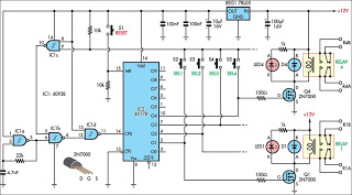
Relay Selector Pushbutton circuit and explanation
This circuit is designed for use in a hi-fi showroom, allowing for the selection of different speakers to connect to a stereo amplifier for comparative listening. It can also serve similar applications where only one device from a set needs...
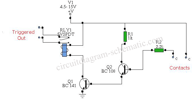
Water Activated Relay circuit board
The circuit diagram represents a water-activated relay circuit. This circuit employs two transistors configured as a high-gain compound pair. The transistors used are 2N2222A for T1 and T2, which may also be substituted with BC108. The current gain is determined...
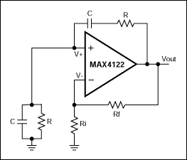
Nodal Analysis of Op Amp Circuits
This application note explains how the transfer function of most operational amplifier circuits can be derived through a straightforward process of nodal analysis.
The transfer function of operational amplifier (op amp) circuits is a critical aspect for understanding their behavior in...
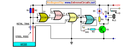
Water Pump Relay Controller Circuit Schematic
This circuit utilizes a relay to control a water pump for automatic level regulation of a water reservoir or well. The shorter steel rod acts as a high water sensor, while the longer rod serves as a low water sensor....
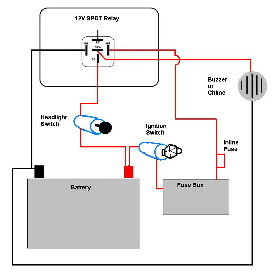
motorcycle headlight with single spdt relay
A bike equipped with a 35-watt HS1 bulb is being upgraded to a brighter headlight using an H4 60/65-watt xenon bulb. An expert recommended using relays due to the increased power requirements of the new bulb. Research conducted on relay...

Relay Fuse For Power Supplies Circuit
A method of adding overload protection to a power supply using a relay is shown. In each circuit, the relay must be reset by a momentary switch using a charge on capacitor C2. This prevents overload if the short still...
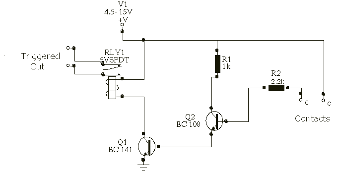
Water Activated Relay
In his circuit Marin has used two transistors wired as a high gain compound pair. Transistor T1 may be a 2N2222A and T2 a BC108. The current gain will be the product of each transistors beta, which will be a...
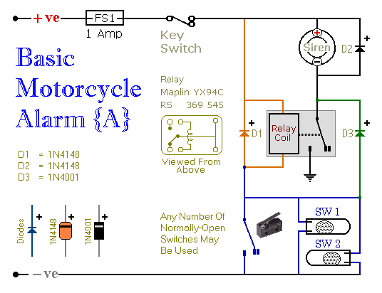
motorcycle alarms numbers
These are two easy-to-build relay-based alarms that can be used to protect motorcycles, among other applications. Using relays with 6-volt coils will safeguard a "Classic Bike." Both alarms are compact, with completed boards occupying approximately half a cubic inch (8...

Tr circuit
R1 and R2 are carbon composition resistors labeled as Va or Vi. K1 is a 12 V DPDT DIP relay. Illustration A demonstrates the connection of the relay contacts for use with a separate transmitter-receiver combination. The circuit is designed...