


LM565 FSK demodulator circuit design electronic project
#FSK demodulator
#LM565
#phase locked loop
#voltage controlled oscillator
#FM demodulation
#telecommunication
#signal processing
#frequency shift keying
#carrier suppression
#electronic project
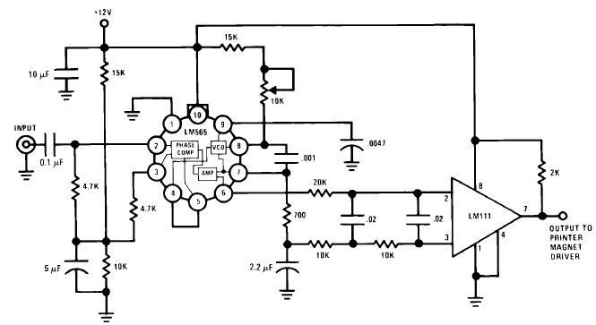
Description: A simple Frequency Shift Keying (FSK) demodulator for 2025 Hz and 2225 Hz can be designed using the LM565, a general-purpose phase-locked loop integrated circuit. This IC includes a stable, highly linear voltage-controlled oscillator that provides low distortion FM demodulation, along with a double balanced phase detector that offers good carrier suppression.
The LM565 serves as an effective solution for demodulating FSK signals due to its integrated components that facilitate the processing of frequency-modulated signals. The design begins with the input of the FSK signal into the phase detector of the LM565. The phase detector compares the incoming signal frequency with the output of the voltage-controlled oscillator (VCO). The VCO is crucial as it generates a frequency that can track the incoming FSK signal frequencies of 2025 Hz and 2225 Hz, allowing for accurate demodulation.
For optimal performance, the LM565 requires proper external component selection. A resistor-capacitor (RC) network is typically used to set the timing characteristics of the phase-locked loop, influencing the response time and stability of the demodulation process. The loop filter, which is also part of the external components, plays a significant role in determining the bandwidth of the VCO and the overall performance of the demodulator.
When designing the circuit, attention must be given to the power supply and grounding to minimize noise, which can affect the integrity of the demodulated signal. The output of the LM565 can be further processed or filtered to retrieve the original data signal, ensuring that the demodulation process maintains the quality and fidelity of the transmitted information.
In summary, the LM565-based FSK demodulator is a versatile and efficient circuit for demodulating signals at specified frequencies, leveraging the IC's built-in capabilities for robust performance in various applications.A very simple FSK demodulator for the 2025 Hz and 2225 Hz can be designed using the LM565 which is a general purpose phase locked loops IC containing a stable, highly linear voltage controlled oscillator for low distortion FM demodulation, and a double balanced phase detector with good carrier suppression.
The LM565 serves as an effective solution for demodulating FSK signals due to its integrated components that facilitate the processing of frequency-modulated signals. The design begins with the input of the FSK signal into the phase detector of the LM565. The phase detector compares the incoming signal frequency with the output of the voltage-controlled oscillator (VCO). The VCO is crucial as it generates a frequency that can track the incoming FSK signal frequencies of 2025 Hz and 2225 Hz, allowing for accurate demodulation.
For optimal performance, the LM565 requires proper external component selection. A resistor-capacitor (RC) network is typically used to set the timing characteristics of the phase-locked loop, influencing the response time and stability of the demodulation process. The loop filter, which is also part of the external components, plays a significant role in determining the bandwidth of the VCO and the overall performance of the demodulator.
When designing the circuit, attention must be given to the power supply and grounding to minimize noise, which can affect the integrity of the demodulated signal. The output of the LM565 can be further processed or filtered to retrieve the original data signal, ensuring that the demodulation process maintains the quality and fidelity of the transmitted information.
In summary, the LM565-based FSK demodulator is a versatile and efficient circuit for demodulating signals at specified frequencies, leveraging the IC's built-in capabilities for robust performance in various applications.A very simple FSK demodulator for the 2025 Hz and 2225 Hz can be designed using the LM565 which is a general purpose phase locked loops IC containing a stable, highly linear voltage controlled oscillator for low distortion FM demodulation, and a double balanced phase detector with good carrier suppression.
Voltage Controlled Oscillator
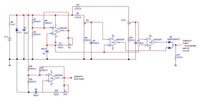
The goal is to control the speed of a 6-volt brush DC motor using a linear potentiometer and to create an oscillating speed effect, with the oscillation frequency also adjustable via a linear potentiometer. The desired complete cycle peak-to-peak duration...
Interpolating Scanner Circuit
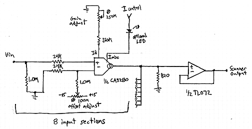
This design is for an interpolating scanner, a circuit featuring multiple signal inputs, a control voltage input, and a signal output. The output selectively transitions between inputs, smoothly fading from one to the next as the control voltage increases. A...
FSK Demodulator/Tone Decoder with RC2211N
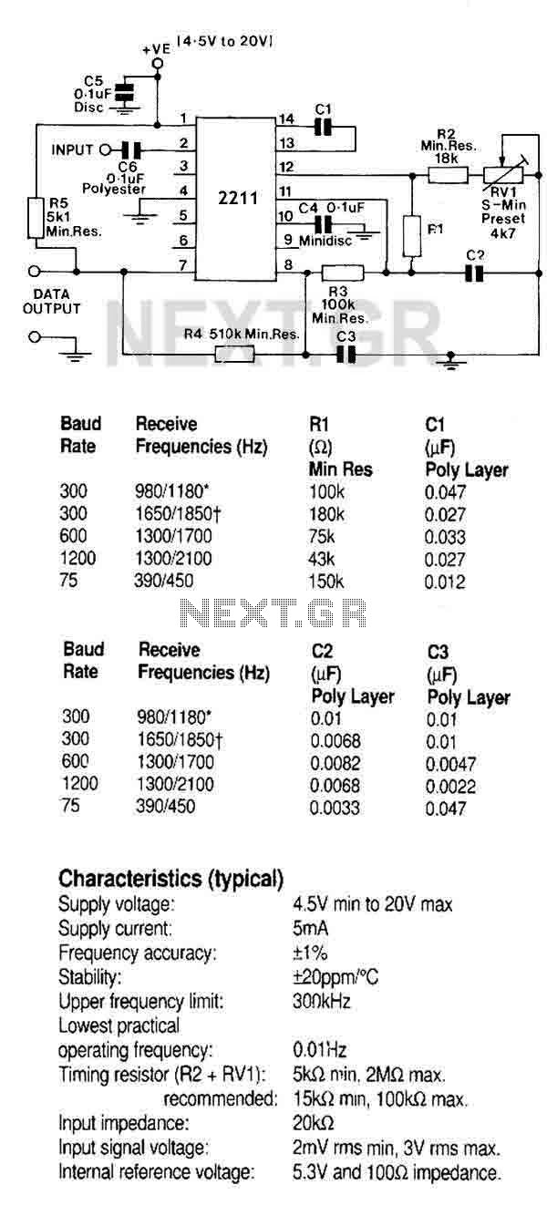
A monolithic phase locked loop for data communications. The IC contains a basic phase locked loop for tracking an input signal within the pass band, a quadrature phase detector which provided carrier detector and an FSK voltage comparator which provides...
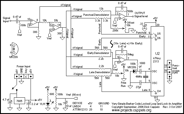
Locked Loop Synchronous Demodulator
A simple, low component count phase locked loop that locks onto and detects the amplitude of an incoming baseband 7 bit Barker code using a switched resistor demodulator that is driven directly by a microcontroller's output pins. Balanced modulators using...
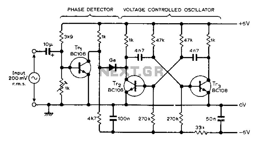
AF locked loop circuit diagram
The circuit MVBR utilizes a traditional two-transistor configuration along with other components to create a simple phase-locked loop (PLL). The transistor TR1 and diodes function as a logic gate, activating during half periods of the input waveform of the voltage-controlled...
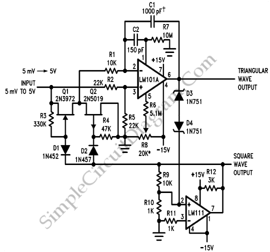
10 Hz to 10 Khz Voltage Controlled Oscillator
A voltage-controlled oscillator (VCO) is an oscillator whose frequency is regulated by a voltage signal. The VCO discussed here can generate both triangular and square wave outputs. The control voltage can be adjusted between 5 mV and 5 V, resulting...
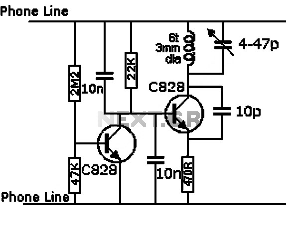
LM359 Voltage Controlled Oscillator Circuit
A voltage-controlled oscillator (VCO) operates similarly to a voltage-to-frequency converter (VFC). Its output frequency is determined by a control voltage input. In the circuit diagram, 'd' represents the amplifier input voltage, which is set to 0.6V, while 'h' denotes the...
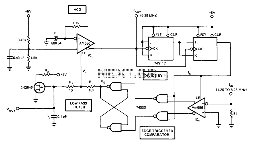
Full-band phase locked loop circuit diagram fast
A circuit diagram of a phase-locked loop utilizes an AM686 latched comparator as a voltage-controlled oscillator, along with a TTL latch connected to generate edge-triggered comparators. The VCO and its comparison with the low-pass filter consisting of R1, R2, and...
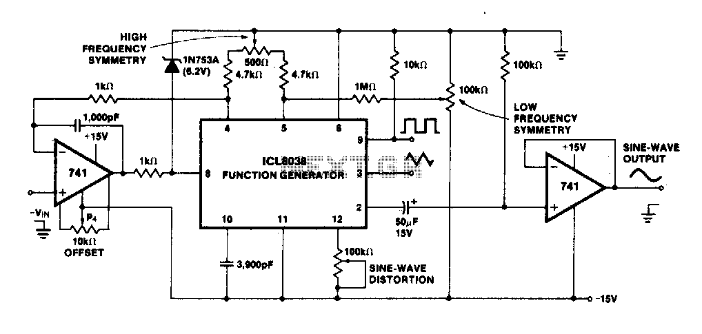
Precision voltage controlled oscillator
The linearity of the input sweep voltage in relation to the output frequency is significantly enhanced by utilizing an operational amplifier.
The utilization of an operational amplifier (op-amp) in electronic circuits is a common practice to improve the linearity of input-output...