


Thumbwheel programmable interval timer
#programmable timer
#interval timer
#relay outputs
#BCD-encoded switches
#thumbwheel switches
#timing control
#SPST switches
#WD-55
#time management
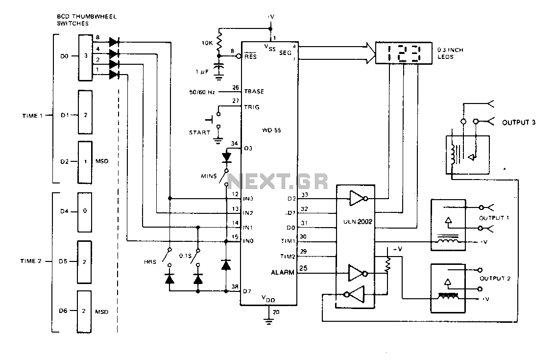
Description: The device is a switch programmable on/off or interval timer that features three relay-switched outputs. Output one activates for the duration of time one, output two activates for the duration of time two, and output three activates for the duration of both time one and time two. The timing data is input through six BCD-encoded thumbwheel switches. Additionally, three SPST switches allow the WD-55 to interpret the data as NNN seconds, NNN minutes, or NNN hours. The LED display indicates the remaining time and the countdown during operation. As the data is input via switches, the display can be removed. Furthermore, since the timing information is sourced from the switches, the data remains nonvolatile and does not require battery backup.
The programmable timer circuit operates by utilizing a microcontroller that processes the input from the six BCD-encoded thumbwheel switches. Each thumbwheel switch corresponds to a specific digit in binary-coded decimal format, allowing for precise timing settings ranging from seconds to hours. The three SPST switches serve as mode selectors, enabling the user to define whether the input timing is interpreted as seconds, minutes, or hours.
The microcontroller's firmware is designed to interpret the BCD inputs and convert them into a time duration that controls the relay outputs. The three relay-switched outputs are operated based on the programmed durations, allowing for sequential or simultaneous activation of connected devices. The first output is activated for the time set by the first thumbwheel switch, the second output for the duration set by the second thumbwheel switch, and the third output remains active for the total duration of both the first and second outputs.
An integral part of the circuit is the LED display, which provides real-time feedback on the countdown process. During operation, the display shows the time remaining until the next relay activation, enhancing user interaction and control. The design eliminates the need for battery backup due to the nonvolatile nature of the data input via the thumbwheel switches.
In summary, the circuit is designed for reliability and ease of use, providing a versatile solution for timing applications without the complications of volatile memory or battery dependence. This programmable timer is suitable for various applications, including automation systems, industrial controls, and home automation projects.Switch programmable on/off or interval timer, has three relay-switched outputs. Output one is active for the duration of time 1, output two is active for the duration of time 2, and output three is active for the duration of both one and two. Timing data is input through 6 BCD-encoded thumbwheel switches. Three SPST switches inform the WD-55 to interpret this data as NNN seconds. NNN seconds, NNN minutes, or NNN hours The LED display will show the time remaining and the countdown when operating. Since the data is input through switches, the display may be deleted. Also, since the timing information is read from switches, the data is nonvolatile and no battery backup is required.
The programmable timer circuit operates by utilizing a microcontroller that processes the input from the six BCD-encoded thumbwheel switches. Each thumbwheel switch corresponds to a specific digit in binary-coded decimal format, allowing for precise timing settings ranging from seconds to hours. The three SPST switches serve as mode selectors, enabling the user to define whether the input timing is interpreted as seconds, minutes, or hours.
The microcontroller's firmware is designed to interpret the BCD inputs and convert them into a time duration that controls the relay outputs. The three relay-switched outputs are operated based on the programmed durations, allowing for sequential or simultaneous activation of connected devices. The first output is activated for the time set by the first thumbwheel switch, the second output for the duration set by the second thumbwheel switch, and the third output remains active for the total duration of both the first and second outputs.
An integral part of the circuit is the LED display, which provides real-time feedback on the countdown process. During operation, the display shows the time remaining until the next relay activation, enhancing user interaction and control. The design eliminates the need for battery backup due to the nonvolatile nature of the data input via the thumbwheel switches.
In summary, the circuit is designed for reliability and ease of use, providing a versatile solution for timing applications without the complications of volatile memory or battery dependence. This programmable timer is suitable for various applications, including automation systems, industrial controls, and home automation projects.Switch programmable on/off or interval timer, has three relay-switched outputs. Output one is active for the duration of time 1, output two is active for the duration of time 2, and output three is active for the duration of both one and two. Timing data is input through 6 BCD-encoded thumbwheel switches. Three SPST switches inform the WD-55 to interpret this data as NNN seconds. NNN seconds, NNN minutes, or NNN hours The LED display will show the time remaining and the countdown when operating. Since the data is input through switches, the display may be deleted. Also, since the timing information is read from switches, the data is nonvolatile and no battery backup is required.
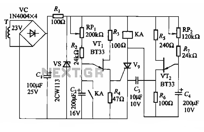
Timing SCR control motor reversing circuit
The circuit depicted in Figure 3-69 is designed for applications requiring frequent timing control for motor reversing operations. In this configuration, thyristors V1, V2, and V7 are utilized for positive control of motor rotation, while thyristors V3, V4, V5, and...
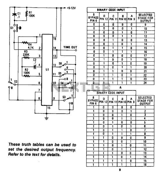
Long-Interval Programmable Timer
Using an RC oscillator, an up to 24-stage ripple counter (O) 16777216 or 2^24, and a 0.1-Hz count rate, with R2 = 39 kΩ, C2 = 0.001 µF, and R4 = 220 kΩ, the count cycle would take approximately 654...
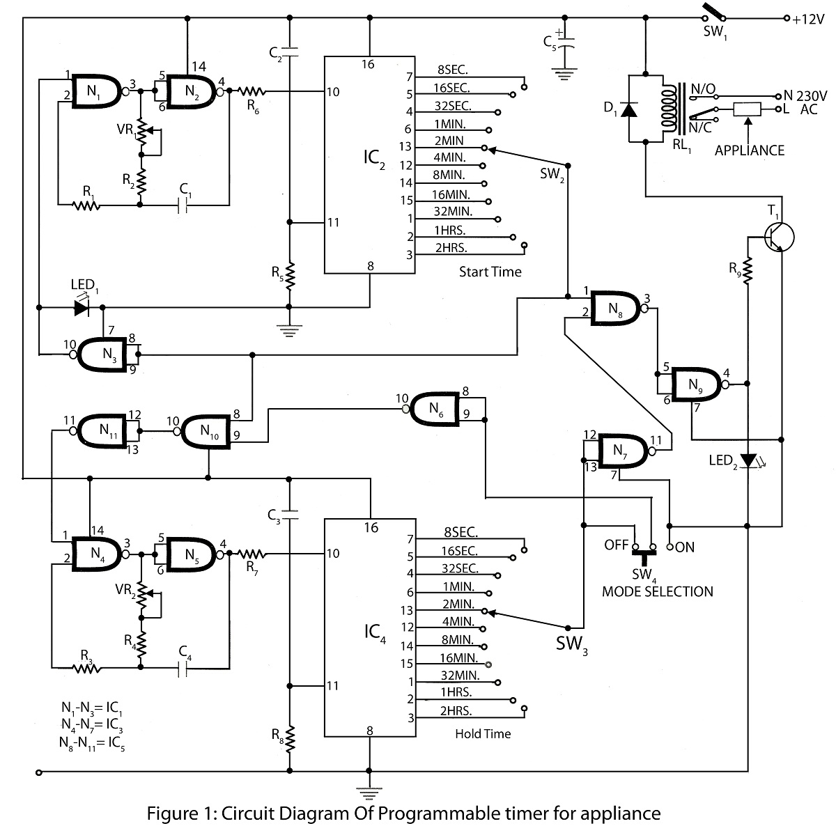
Programmable timer for appliance
A programmable timer for an appliance circuit is an advanced timer that controls the operation of the appliance. The timer can be set for durations ranging from 8 seconds to 2 hours. A circuit diagram of the programmable timer for...
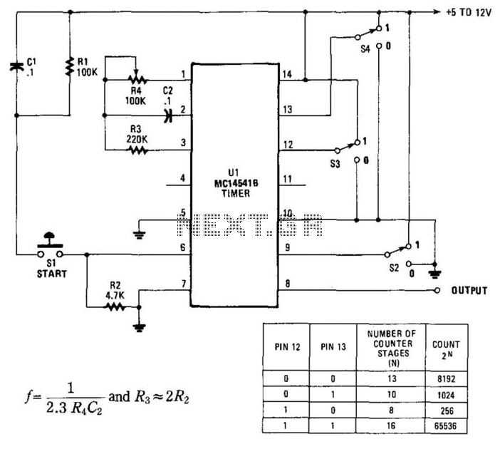
Programmable Timer For Long Intervals
By utilizing an RC oscillator and a programmable divider, this counter can operate for extended periods. The interval oscillator functions at a frequency determined by specific component values: for instance, with R1 = 390 kΩ and C2 = 10 µF,...
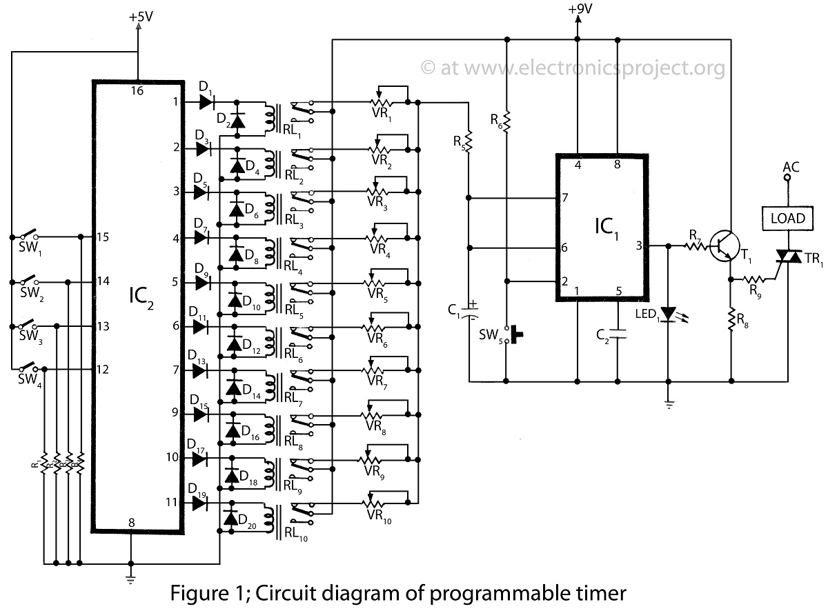
Programmable Timer of timer circuit
The programmable timer presented on this website is a straightforward design utilizing only two integrated circuits (ICs). It covers a wide range of applications and includes descriptions of various timer projects.
The programmable timer circuit typically consists of two primary integrated...
Timing SCR control motor reversing circuit
The circuit depicted in Figure 3-69 is designed for applications requiring frequent timing control for motor reversing operations. In this configuration, thyristors V1, V2, and V7 are utilized for positive control of motor rotation, while thyristors V3, V4, V5, and...