

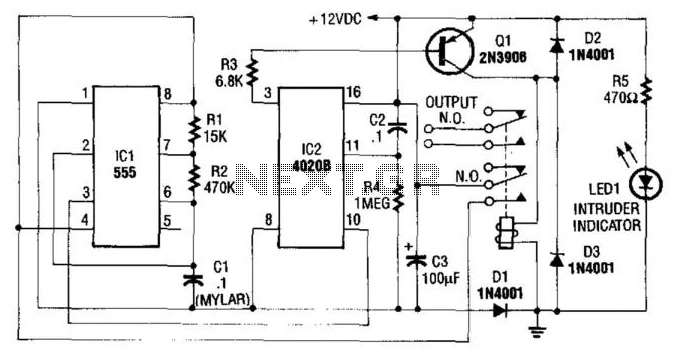

Auto Turn-Off Alarm With 8-Minute Delay
This circuit uses a NE555 timer and CD4020B. When +12 Vdc is applied to the circuit, the output of ...
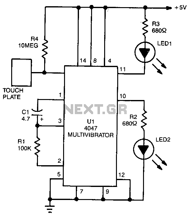
Positive-triggered-touch-circuit
LED1 and LED2 indicators turn on and remain on, each time the circuit is triggered. During the timing cycle, U1 "s Q output at pin 10 becomes positive when t...
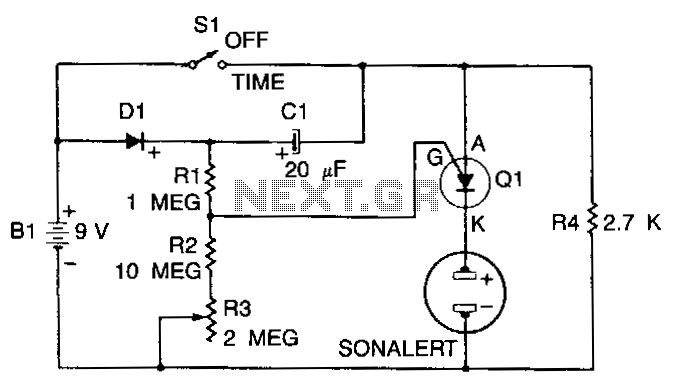
Three-minute-timer
When Sl is off, Cl charges to within 0.5 V of the battery voltage through diode Dl and resistor R4. When Sl is closed, tbe anode of tbe PUT rises to the positi...
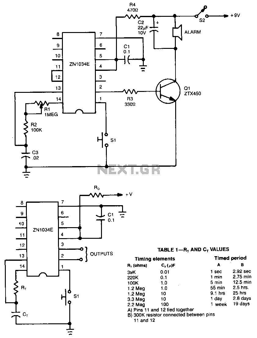
Long-time-timer
When used as a stand-alone device, ZN1034E from Ferranti can provide timed intervals ranging from 1 second to 19 days, although the rc time constant is only 22...
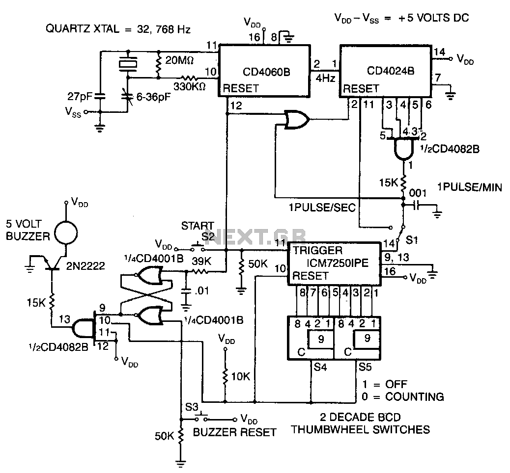
Cmos-precision-programmable-laboratory-timer
The time base is first selected with Sl set for seconds or minutes, then units 0-99 are selected on the two thumbwheel switches S4 and S5. Finally, switch S2 i...
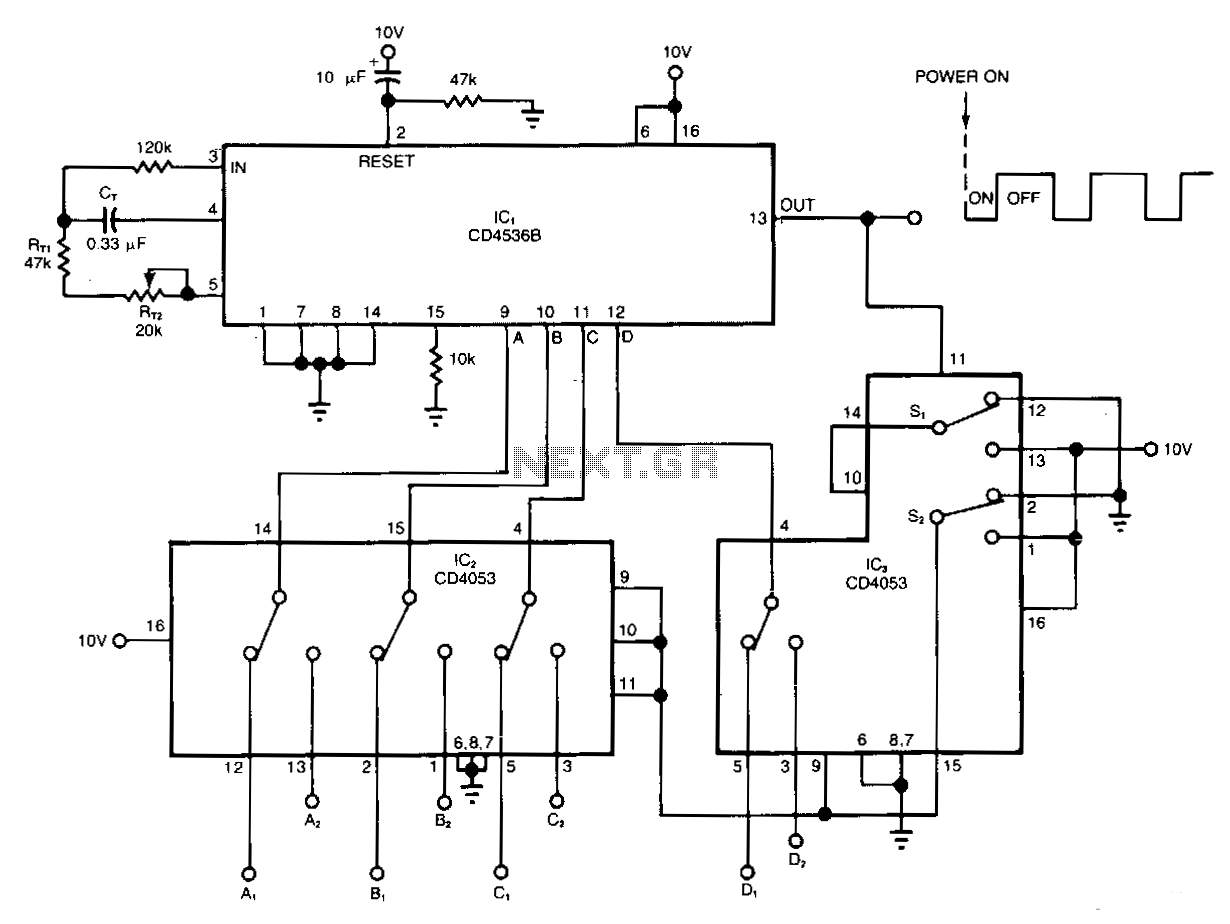
Sequential-timer
The timer circuit shown gives independent control of the output"s on and off intervals, which can range from 0.055 seconds to 30 minutes, relatively unaffected...
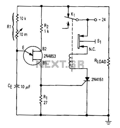
Simple-time-delay
After the first cycle. the relay will normally be energized. When normally closed pushbutton 51 is activated, the SCR turns off, the relay is de-energized, a...
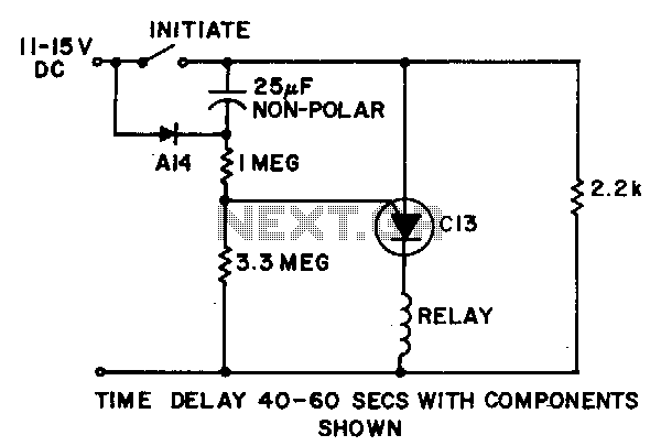
Timing-threshold-and-load-driver
Power is applied to the circuit with the initiate switch open. The 25-JtF capacitor charges through the A14, or equivalent, diode and 2.2-KO resistor to full...
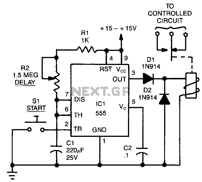
Electronic-time-delay
The time delay, T, in seconds is: T = 1.1 x Cl x (Rl + R2). The resistances are in megohms and capacitances in microfarads. The sum of R1 and R2 should not be ...
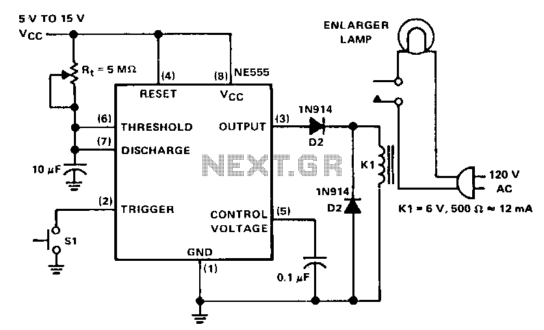
Darkroom-enlarger-timer
The NE555 circuit is a basic one-shot timer with a relay connected between the output and ground. It is triggered with the normally open momentary contact swit...
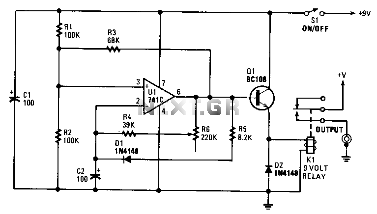
Slide-show-timer
You can set the interval from about 5-30 seconds. A relay operates the slide-change mechanism. Op amp Ul forms a sort of Schmitt trigger. Resistors Rl and R2 b...
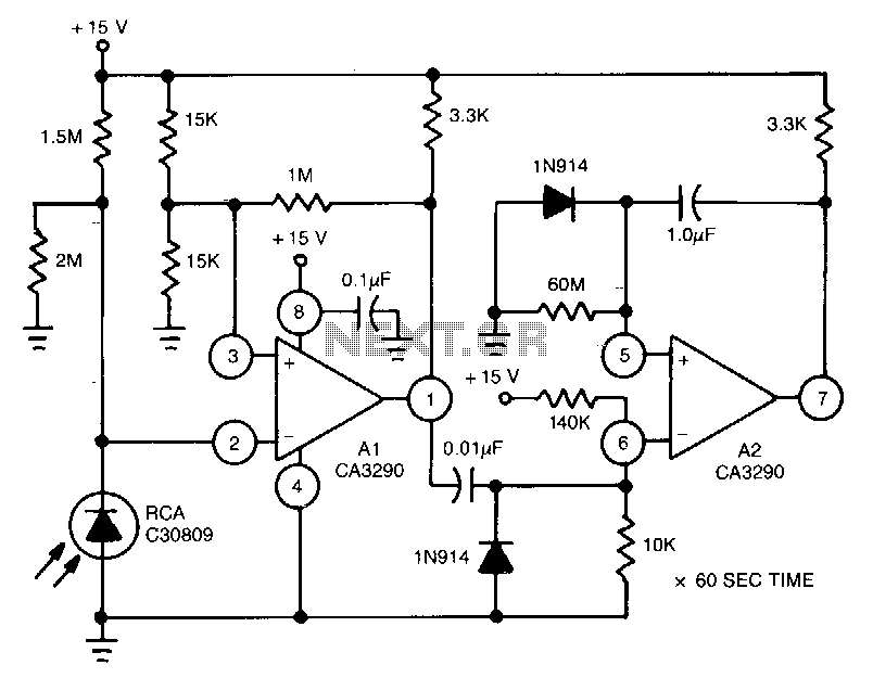
Light-controlled-one-shot-timer
This circuit uses Al of the CA3290 BiMOS dual voltage comparator to sense a change in light diode current. A2, a one-shot timer, is triggered by the Al output....
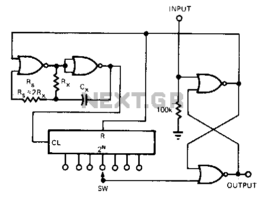
Low-power-wide-range-programmable-counter
This CMOS circuit can be used as a 1-shot time delay switch and general-purpose timer. The circuit consists of a gated oscillator and a latch made from one CD4...
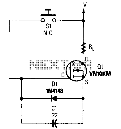
Automatic-shutoff
When Sl is depressed, Cl begins to charge to the supply voltage. That places a forward bias on the gate of Ql turning it on and supplying current to load res...
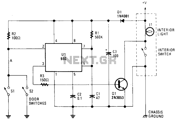
Courtesy-light-extender
The circuit keeps the courtesy light on for 30 seconds after you close the door. The lead from the door switch is removed and connected to the 555 circuit. The...
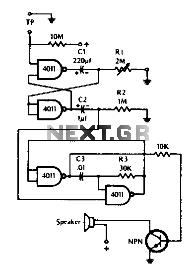
Timer
The timer can be used wherever time periods of up to seven minutes duration are needed. To turn on just touch the turn-on plate, and after the selected time has...
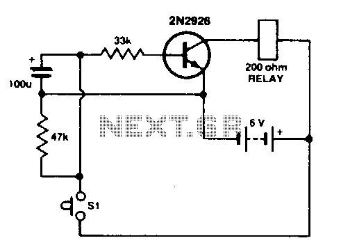
Simple timer
Press SI. The 100 µF electrolytic capacitor rapidly charges up at about 0 V. The transistor will be forward biased, and collector current will flow operating...
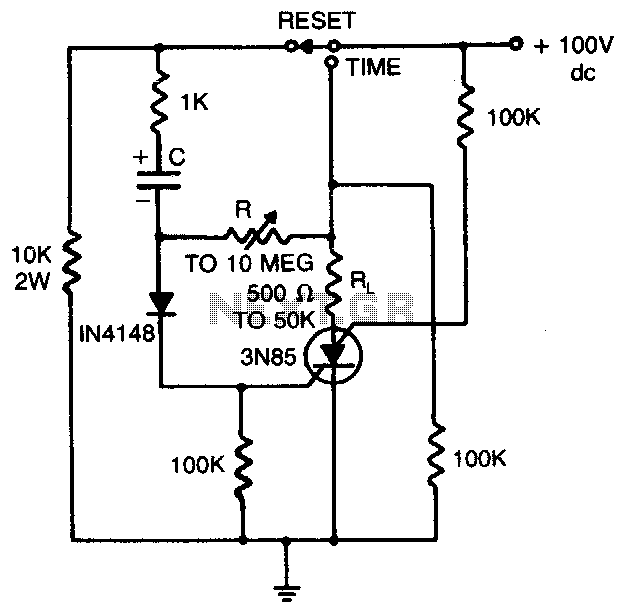
Timing circuit
Load current starts approximately 0 RC...
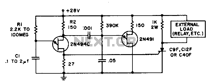
Precision solid state time delay circuit
Time delays from 0 milliseconds to over three minutes are possible with this circuit without using a tantalum or electrolytic capacitor. The timing interval is ...
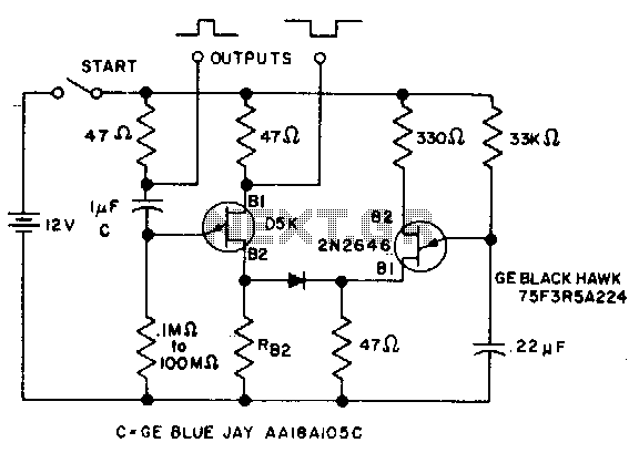
0.1 To 90 second timer
The timer interval starts when power is applied to circuit and terminates when voltage is applied to load. 2N2646 is used in oscillator which pulses base 2 of D...