
transistor power amplifier circuit diagram

A Class AB transistor audio power amplifier is designed to provide high-quality amplification for audio signals while maintaining efficiency. This circuit typically employs a complementary push-pull configuration, using both NPN and PNP transistors to enhance performance and reduce distortion.
The circuit consists of several key components: input capacitors, biasing resistors, feedback network, and output transistors. The input stage often includes a capacitor to block DC while allowing AC audio signals to pass through. This is followed by a biasing network that sets the operating point of the transistors, ensuring they operate in the linear region for optimal audio fidelity.
The complementary output stage, made up of NPN and PNP transistors, allows the amplifier to handle both halves of the audio waveform efficiently. This configuration minimizes crossover distortion, which is common in simpler Class B designs. The output transistors are typically driven by a driver stage that provides the necessary gain and current to drive the load, usually a speaker.
Feedback is employed in the circuit to improve linearity and reduce harmonic distortion. A portion of the output signal is fed back to the input stage, allowing for real-time adjustments to the gain and improving overall stability.
Power supply considerations are also critical in Class AB amplifiers. The circuit requires a dual power supply, providing both positive and negative voltages to the output stage. This ensures that the amplifier can reproduce the full range of audio signals without clipping.
Thermal management is another important aspect, as the output transistors can generate significant heat during operation. Heat sinks are often used to dissipate this heat and maintain the reliability of the amplifier.
Overall, the discrete Class AB transistor audio power amplifier is a versatile and efficient solution for audio amplification, providing a good balance between sound quality and power efficiency.Discrete Class AB Transistor Audio Power Amplifier Circuit Diagram This is a class AB transistor power amplifier. It is a simple amplifier to.. 🔗 External reference
Related Circuits
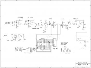
This is an easy-to-build surround sound processor circuit utilizing the digital delay processing method. This audio processor does not employ any specialized function integrated circuits that are difficult to obtain, and it is designed using only common-purpose integrated circuits....
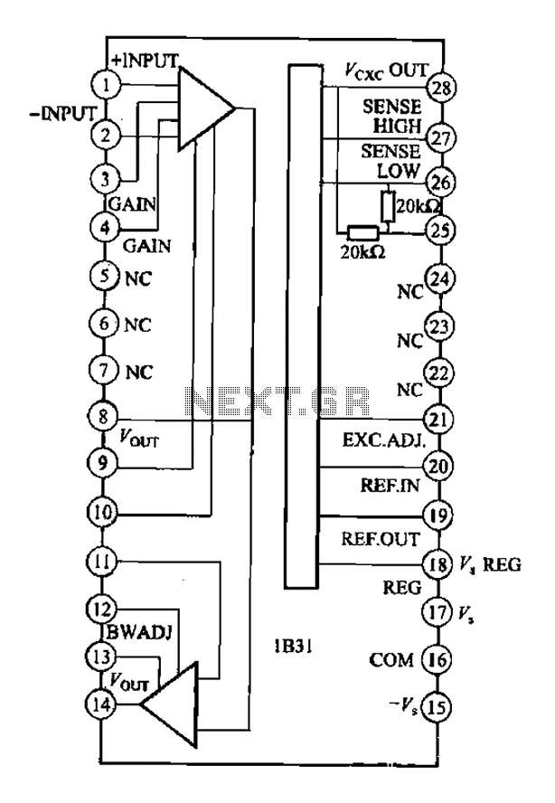
The Analog Devices 1831 is designed for strain gauge signal conditioning applications. It features an internal low drift input of 0.25V with a gain of 1000, exhibiting excellent linearity with a maximum deviation of 0.005%. The IC operates with...
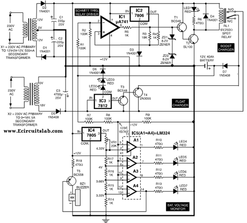
This circuit illustrates the use of the 7806 IC in an automatic battery charger circuit diagram. It is designed for a car battery with an approximate rating of 40 Ah. The automatic battery charger circuit utilizing the 7806 integrated circuit...
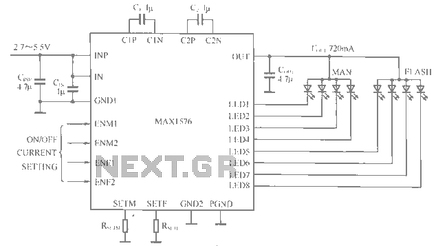
The MAX1516 charge pump drives up to 8 white LEDs with constant current regulation to achieve uniform light intensity, capable of delivering up to 30mA per LED for backlighting. The flash group LEDs (LED5 to LED8) are individually controlled,...
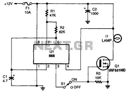
The headlight flasher is a 555 oscillator/timer configured as an astable multivibrator (oscillator). Its input is used to drive the gate of an IRF53IND hexFET, which acts as an on/off switch, turning the lamp on and off at an...
To omit the balance control when using separate potentiometers for the volume controls, refer to the balance control notes on the 7-tube output amplifier page. A schematic was utilized to build a modified version with separate bass and treble...