
Nine Tube Stereo Amplifier 1
The described circuit pertains to a 7-tube output amplifier with a focus on sound quality and user customization. The omission of the balance control allows for a more straightforward design when separate volume controls are used. The inclusion of dedicated bass and treble controls for each channel enhances the versatility of the amplifier, enabling users to tailor the audio output to their preferences.
The relocation of the balance control serves a dual purpose: it minimizes the load on the potentiometer, which can improve reliability and longevity, and it potentially enhances the overall audio fidelity by optimizing the signal path. The addition of switchable inputs allows for flexibility in connecting various audio sources, catering to diverse user needs.
The use of handmade parts boards reminiscent of Fender amplifiers suggests a commitment to quality and craftsmanship. The initial tests with the Grundig Yacht Boy 300 indicate that the amplifier is capable of delivering high-quality audio, making it suitable for a range of applications from casual listening to more critical audio environments.
The aesthetic considerations, such as the silver top cage and the overall chassis layout, contribute to both the visual appeal and the functional integrity of the amplifier. The shielding partition between the power supply and amplifier stages is a critical design feature that mitigates electromagnetic interference, further enhancing sound clarity and reducing hum.
The careful arrangement of components within the chassis, especially noted in the underside views, reflects best practices in electronic design. Proper lead dress and component placement are essential for minimizing noise and maximizing performance, particularly in high-fidelity audio applications.
Overall, this amplifier design exemplifies a thoughtful approach to both technical performance and aesthetic appeal, making it a noteworthy project for enthusiasts and professionals alike. The encouragement for others to share their builds fosters a community of innovation and knowledge sharing within the audio engineering field.If you want to omit this balance control, such as when using separate pots for the volume controls, see the balance control notes on the 7-tube output amplifier page. "Wes, I used the schematic posted on your site, and built this. modified slightly with separate bass and treble on each channel. also, I moved the location of the balance control in the circuit, to lessen the load on the pot. I gave it two sets of switchable inputs. I used handmade parts boards. (similar to a fender) at this point I was testing it out. sounds very nice. I`m driving it with a Grundig Yacht Boy 300. I have to go back in to add the filter choke. I was anxious to try it out. " As You can see from the photos, George did a nice job with chassis layout, and has just done a real first-class job with the layout and construction. The silver top cage gives the finished rig a nice "classic" look. 1-25-12 DC has written me several times with questions and comments about this schematic and was kind enough to share a few photographs of the amplifier he built from it.
He has told me it sounds as good as it looks, and I believe it. DC did not use a commercially made chassis box, but built it himself and the results are very nice with the layout, color finish and wood ends. Also note the shielding partition DC built between the power supply and amplifier stages. DC chose the asymmetrical chassis layout you see here for minimal hum. Note the very clean layout that DC designed for the circuit components in the chassis underside views.
DC has been very picky about component and interconnect lead dress, and I believe it has paid off in the amp`s performance. If you too have built this amp, then email me a few pictures if you like, and I`ll add them here with a few comments.
Just email them to the address shown in the contact info on the Radio Page in the link below. 🔗 External reference
Related Circuits
As readers may know, there are several power amplifier projects, including two that utilize integrated circuit (IC) power amplifiers, commonly referred to as power op-amps. Both of these projects have gained popularity, and this new project is not intended...

This is a standard amplifier based on LM 1875. It can deliver 20 W, with an 8 Ω speaker and 60V power supply even 30 W. The capacitors C4 and C5 should preferably be as close to the IC down....
The next stage operates in conjunction with the first stage and is fully complementary. A cascode circuit is included to enhance the linearity of the amplifiers. This cascode circuit requires a constant reference voltage for biasing to activate the...
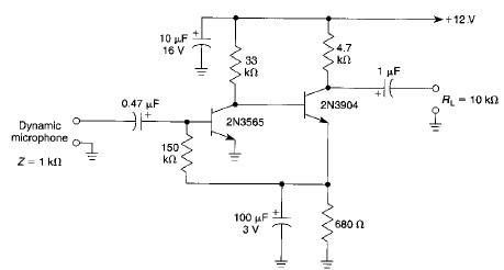
This microphone preamplifier electronic project is based on transistors and is capable of approximately 70 dB or more gain at audio frequencies. The gain of this circuit is roughly equal to the product of the hfe (current gain) of...
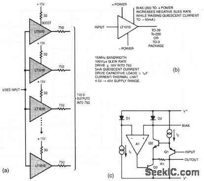
The resistors in the output lines are used to isolate reflections from unterminated lines. If the line characteristics are known, the resistors can be removed. To satisfy NTSC gain-phase requirements, a small-value boost resistor is employed. Figures 3-27B and...
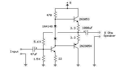
This weblog focuses on electronic circuit schematics, PCB design, DIY kits, and electronic project diagrams. The following describes a small audio amplifier, similar to those found in medium-sized transistor radios. The input stage is biased to ensure equal power...