
clap switch circuit here is hobby
The circuit operates by first detecting the sound of a clap through the microphone, which is typically a small electret microphone. The microphone's output is an AC signal that is biased by R1 to ensure it is suitable for amplification. The transistor Q1 is configured in a common emitter arrangement, providing significant voltage gain to the weak microphone signal. This amplification is crucial, as it allows the subsequent flip-flop stage to operate reliably by ensuring that the signal level is sufficient to trigger the transistors Q2 and Q3.
The bistable multivibrator configuration is essential for creating a stable on/off output based on the input trigger. The two transistors are arranged such that when one is turned on, the other is turned off, creating a stable state. The output from the flip-flop can be connected to various devices, but since its current capacity is limited, it is necessary to amplify the output further. The common emitter configuration of Q4 serves this purpose, providing the necessary current to activate the relay.
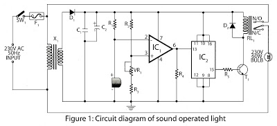
The relay acts as a switch to control higher power devices, isolating the low-power logic circuit from the high-power load. When the relay is energized by the output of Q4, it closes its contacts, allowing current to flow to the connected device, such as a light or fan. This design is particularly useful for hobbyists looking to create interactive electronic projects that respond to sound, showcasing fundamental principles of electronics, including amplification, signal processing, and switching mechanisms. The circuit is not only educational but also practical, offering a hands-on approach to learning about electronic components and their applications.Here is a Hobby Circuit for electronics hobbyists that can switch on & off a light, Fan, Radio etc. by the sound of clap. The sound of clap is received by a small microphone that is shown biased by resistor R1 in the circuit. The microphone changes sound wave in to electrical wave which is further amplified by Q1. Transistor Q1 is used as common em itter circuit to amplify weak signals received by the microphone. Amplified output from the collector of transistor Q1 is then feed to the Bistable Multivibrator circuit also known as flip-flop circuit. Flip flop circuit is made by using 2 Transistor, in our circuit Q2&Q3. In a flip-flop circuit, at a time only one transistor conduct and other cut off and when it gets a trigger pulse from outside source then first transistor is cutoff and 2nd transistor conducts.
Thus output of transistor is either logic-0 or logic-1 and it remains in one state 0 or 1 until it gets trigger pulse from outer source. The pulse of clap which is a trigger for flip-flop which makes changes to the output which is complementary (reverse).
Output of flip-flop which is in the low current form is unable to drive relay directly so we have used a current amplifier circuit by using Q4 which is a common emitter circuit. Output of Q4 is connected to a Relay (Electromagnetic switch) which works like a mechanical switch and it becomes easy for connecting other electrical appliance.
🔗 External reference
Related Circuits
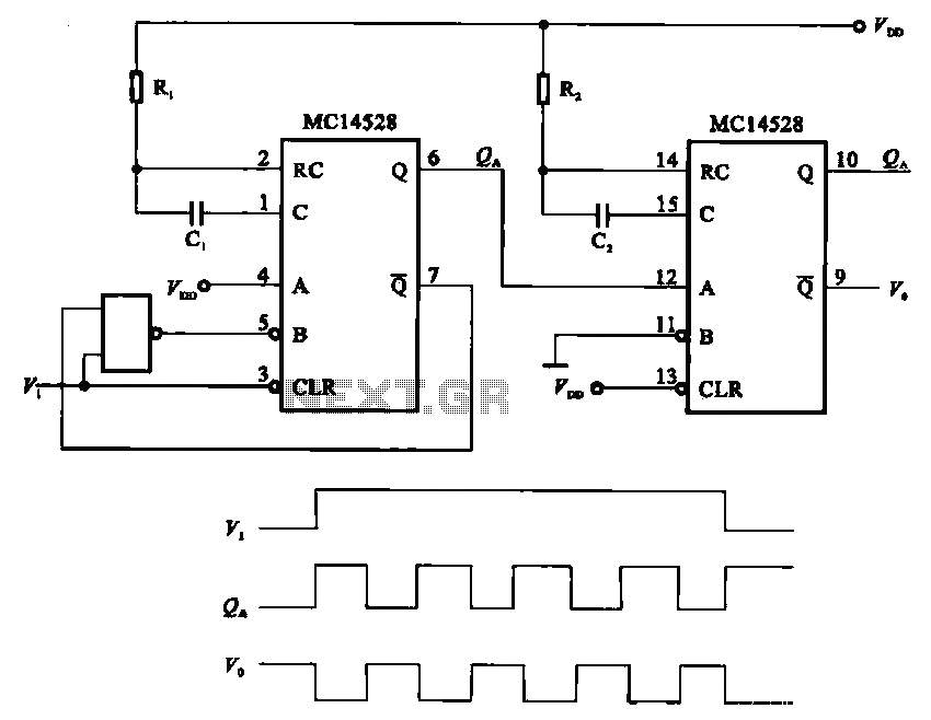
The pulse generating circuit monitors signals using monostable flip-flops. It generates a single-shot output signal based on the input pulse signal. A key signal from the monostable flip-flops is represented in a formula, with the input (V1) and output...
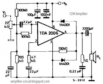
The power amplifier IC TDA2006 provides high output current and has very low harmonic and cross-over distortion. Furthermore, the device incorporates an original (and patented) short circuit protection system that automatically limits the dissipated power to keep the working...
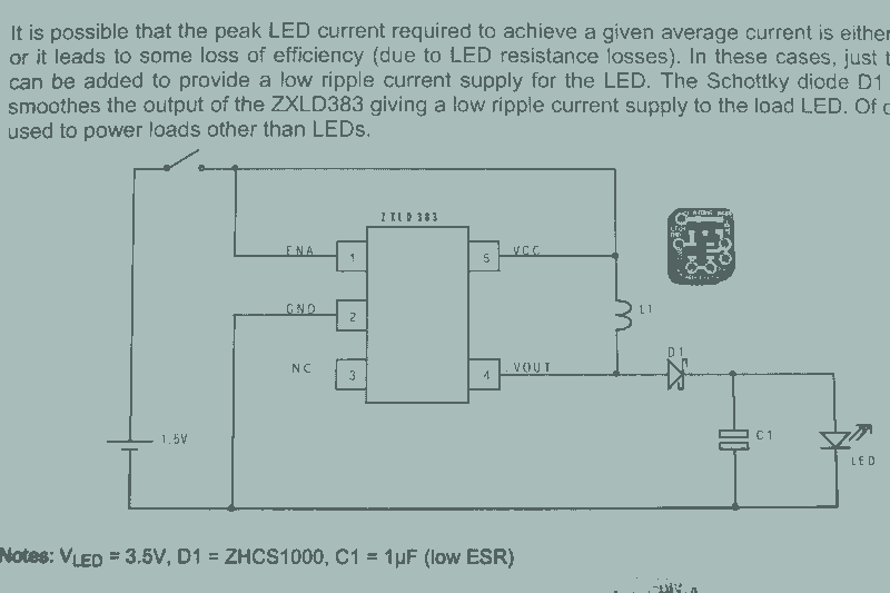
It may seem that due to the numerous flashlight projects undertaken, there is a significant collection of lights. The inductor can be altered to set the current level, but the total current fluctuates with the battery supply, decreasing as...
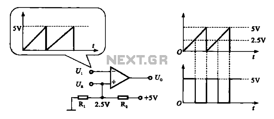
The addition and subtraction functions of an operational amplifier are facilitated through an external feedback network, which places the integrated operational amplifier in a deep state of negative feedback. In this linear region, the relationship between input and output...
The motion sensor switch circuit is a motion sensor-controlled automatic water sprinkler, but an alarm or light function can be easily added as well. The motion sensor switch circuit utilizes a passive infrared (PIR) sensor to detect motion within...
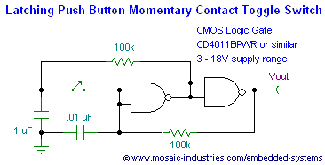
This page presents soft power switch circuits designed for toggling electronic devices ON and OFF with a momentary button press that controls a latching high-side MOSFET power switch. Multiple micropower latching switch circuits are included. Due to their low...