
LED lights using Joule Thief circuits
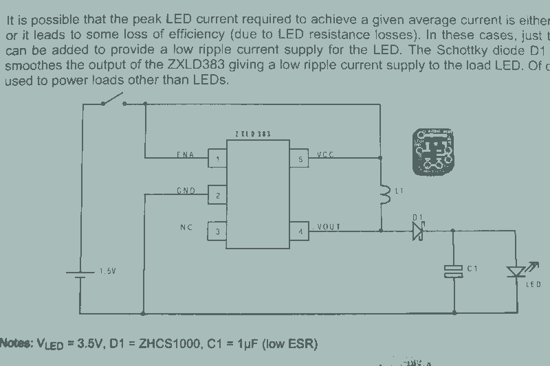
In the context of flashlight circuit design, the use of inductors plays a critical role in controlling the current flow. Inductors are essential components in switch-mode power supplies, which are commonly employed in flashlight circuits to enhance efficiency and extend battery life. By adjusting the inductance value, designers can precisely set the desired current output for the LED or other light sources used in the flashlight.
The circuit typically includes a pulse-width modulation (PWM) controller, which regulates the power delivered to the LED by switching the current on and off at a high frequency. This method allows for fine control over brightness levels while minimizing power loss. The inductor works in conjunction with a capacitor to smooth out the current, ensuring a stable output even as the battery voltage decreases.
As the battery discharges, its voltage drops, which directly affects the current supplied to the circuit. This decline in voltage can lead to a reduced brightness in the LED unless the circuit is designed to compensate for this change. Some designs incorporate feedback mechanisms that monitor the output current and adjust the PWM duty cycle accordingly to maintain consistent brightness levels throughout the battery's discharge cycle.
In summary, the design of flashlight circuits involves careful consideration of inductor selection, PWM control, and battery management to ensure optimal performance and longevity of the light output.You would think that given how many flashlight projects I do that I actually own a lot of lights. I can change the inductor to adjust the current setpoint, but the overall current varies with the battery supply as the battery drains the current lowers 🔗 External reference
Related Circuits

An audio test oscillator circuit typically produces a square wave if the oscillation frequency is low enough in relation to the amplifier's bandwidth. This circuit features a crystal-controlled oscillator designed for low-frequency sine wave generation, characterized by low distortion,...
This circuit utilizes a single 555 Timer IC along with a small transformer to generate high voltage for testing zener diodes with voltage ratings up to 50VDC. The 555 timer operates in astable mode, with the output from pin...
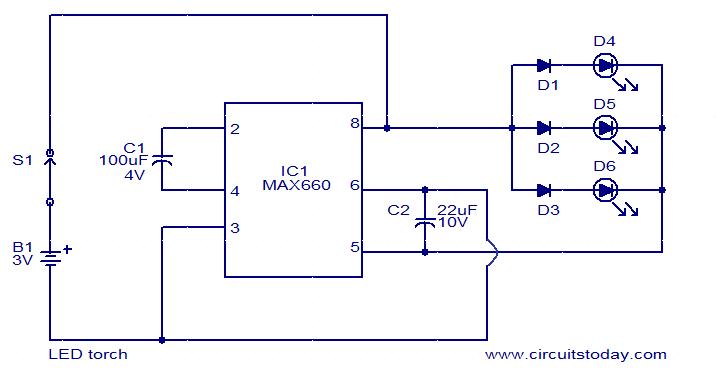
This circuit is a simple LED torch utilizing the MAX660 integrated circuit from MAXIM semiconductors. The MAX660 is a CMOS monolithic voltage converter IC capable of driving three bright white LEDs connected in parallel to output pin 8 of...
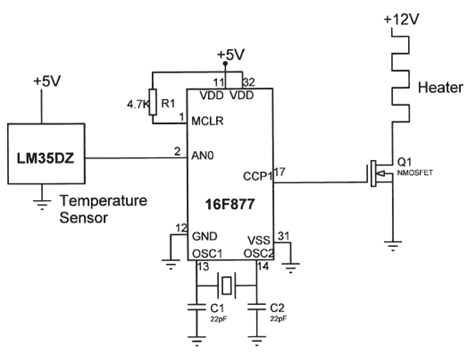
The electrical circuit diagram of this temperature control circuit consists of a 3-pin analog temperature sensor (LM35DZ), a built-in A/D converter microcontroller (PIC16F877), and the heater driver (IRL1004). The temperature control circuit utilizes the LM35DZ, a precision analog temperature sensor...

A simple touch dimmer circuit diagram using the TT6061 IC, which is a touch control integrated circuit used for light dimmer circuits and lamp dimmer circuits. The touch dimmer circuit utilizing the TT6061 IC is designed to provide a user-friendly...
A 10-light LED bar graph is desired, where the LEDs light up sequentially until all are lit, then cycle back down until all are off. The LM3914 - Dot/Bar Display Driver is a simpler analog solution that operates in...