
Motion Sensor Switch for alarm light or water sprinkler
The motion sensor switch circuit utilizes a passive infrared (PIR) sensor to detect motion within a specified range. When motion is detected, the circuit activates a relay that controls the water sprinkler system. The PIR sensor operates by measuring changes in infrared radiation, which occurs when a warm body, such as a human or animal, enters its detection field.
The basic components of the circuit include the PIR sensor, a microcontroller or timer IC, a relay module, and the water sprinkler system. The PIR sensor outputs a high signal when motion is detected, which can be processed by the microcontroller or timer to trigger the relay. The relay acts as a switch that activates the water pump or solenoid valve of the sprinkler system.
For additional functionality, such as an alarm or light, a simple modification can be made. An LED or a buzzer can be connected to the output of the microcontroller. When motion is detected, the microcontroller can simultaneously activate both the relay for the sprinkler and the alarm/light output.
Power supply considerations should be taken into account, ensuring that the circuit is powered adequately, either through a battery or an AC adapter. Furthermore, it is important to incorporate necessary safety features, such as fuses or circuit breakers, to prevent damage to components due to overcurrent conditions.
This motion sensor switch circuit can be effectively used in gardens or lawns to automate watering processes while also providing security through alarm or lighting features upon detecting movement.The Motion Sensor Switch circuit is a motion sensor controlled automatic water sprinkler but you can easily add an alarm/light function too. Before beginni. 🔗 External reference
Related Circuits

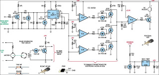
This figure illustrates a block diagram of modern automated systems that incorporate closed-loop feedback for motion control. These systems typically feature a servo system consisting of feedback elements and a motor driver, which work together to provide accurate and...
When driving, it can be difficult to gauge the speed of a vehicle, particularly on straight highways. If the vehicle exceeds a safe speed, it may lead to accidents. Therefore, a Car Speed Alarm circuit is necessary to alert...
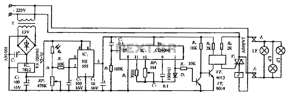
The circuit consists of three parts: a light control section, a time control section, and a power supply section. The light control section utilizes a photoresistor (Rg) and a variable resistor (RP) to detect light levels. During the day,...
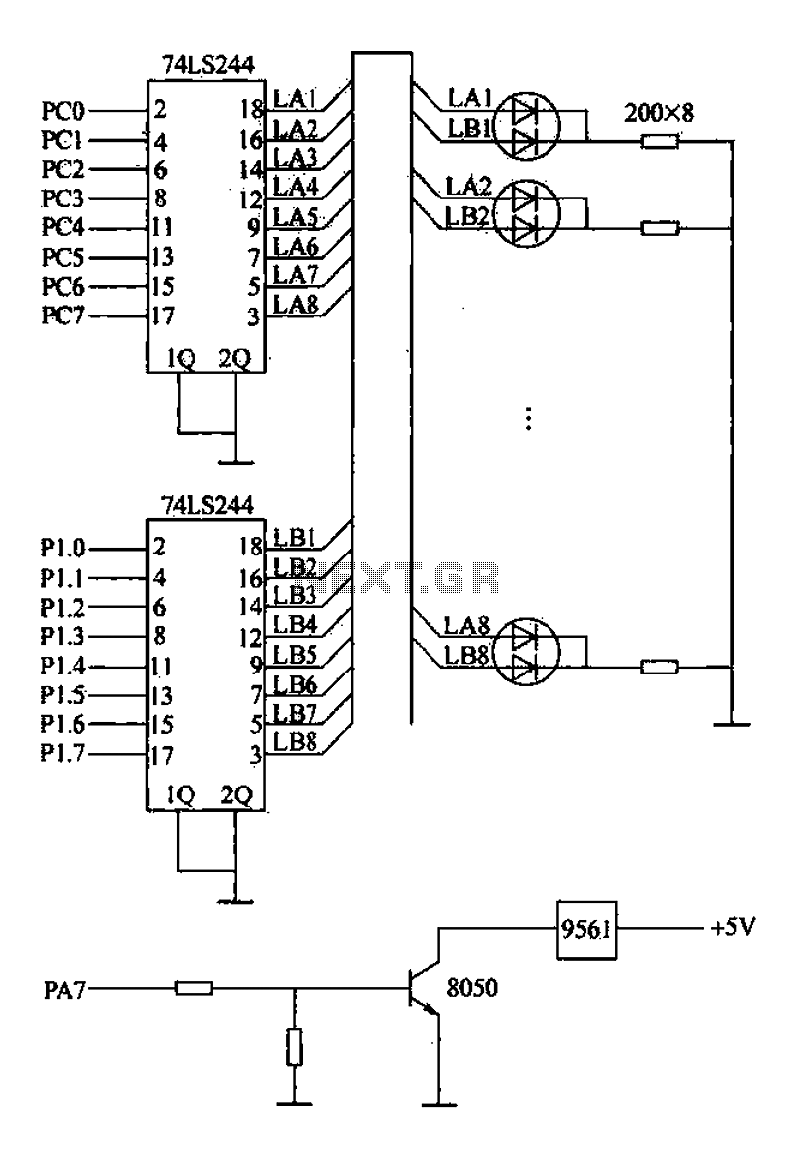
Alarm interface circuitry featuring a two-color light-emitting diode (LED) display. When LAi is at a high level and LBi is low, the green LED lights up; conversely, if LAi is low and LBi is high, the red LED lights...
This simple circuit drives six LEDs in a Knight Rider scanner mode. Power consumption primarily depends on the type of LEDs used, especially when utilizing a 7555 (555 CMOS version). The Knight Rider scanner circuit is designed to create a...
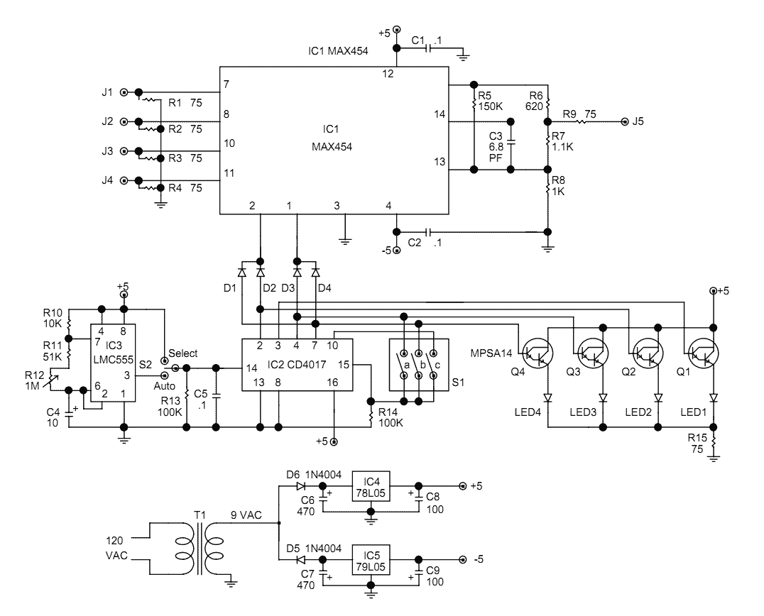
The video switcher described here can display the output of two, three, or four cameras on a single monitor. The number of cameras is set by a DIP switch on the circuit board. That feature avoids blank displays if...
Warning: include(partials/cookie-banner.php): Failed to open stream: Permission denied in /var/www/html/nextgr/view-circuit.php on line 713
Warning: include(): Failed opening 'partials/cookie-banner.php' for inclusion (include_path='.:/usr/share/php') in /var/www/html/nextgr/view-circuit.php on line 713