
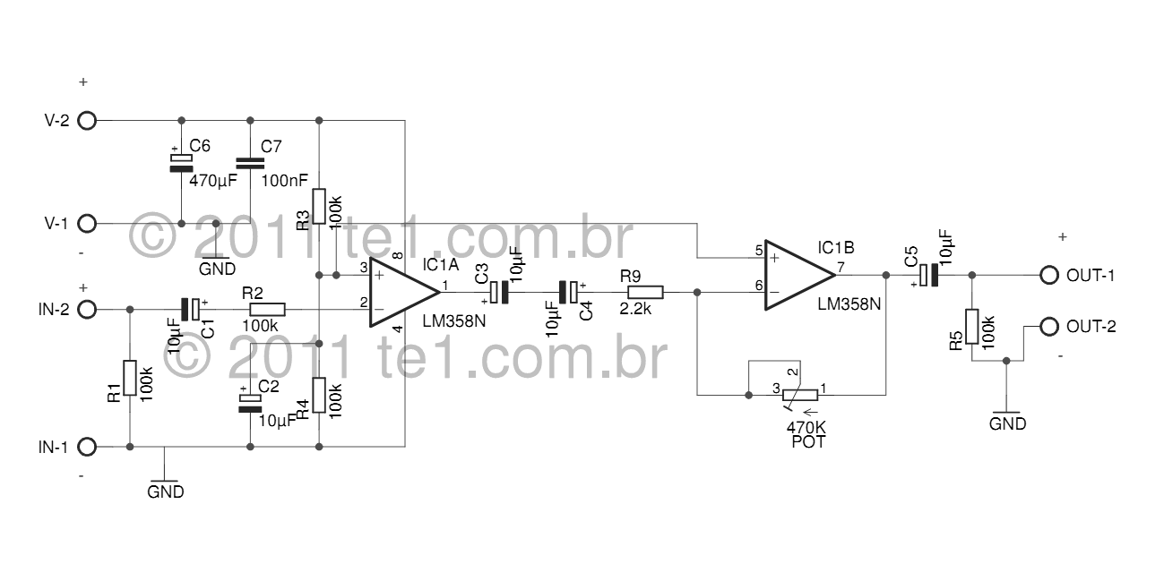
Class A-Designed Symmetrical Audio Preamplifier

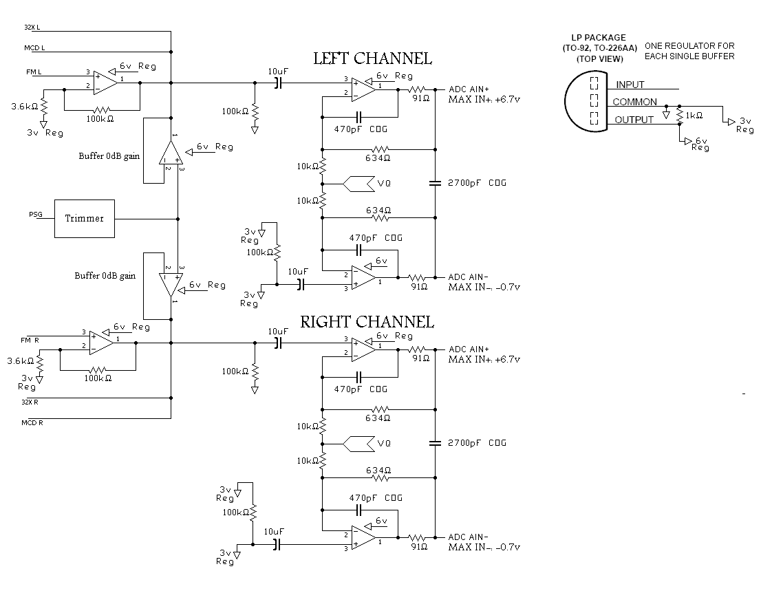
The circuit in question is a preamplifier designed to handle symmetrical audio inputs, which ensures that both positive and negative halves of the audio signal are amplified equally. This is particularly important in audio applications where signal integrity and fidelity are paramount. The output stage of this preamplifier operates in Class A mode, known for its high linearity and low distortion characteristics, making it ideal for high-quality audio amplification.
The schematic typically includes several key components: operational amplifiers (op-amps) for signal amplification, resistors for setting gain and biasing, capacitors for coupling and decoupling, and possibly a power supply section to provide the necessary voltage levels for the op-amps. The symmetrical input configuration may utilize differential input stages to reject common-mode noise, which is beneficial in maintaining audio quality.
In Class A operation, the output transistors conduct over the entire cycle of the input signal, resulting in a linear response that minimizes crossover distortion. This is achieved by biasing the transistors so that they remain in the active region at all times. The trade-off for this linearity is decreased efficiency, as Class A amplifiers tend to dissipate more power as heat.
Overall, the design emphasizes high fidelity and low distortion, making it suitable for high-end audio applications, such as in professional audio equipment or high-quality home audio systems. Proper thermal management and careful component selection are critical to ensure optimal performance and reliability of the preamplifier circuit.The circuit was designed to produce a preamplifier with symmetrical audio input while the output operates in Class A type. Preamplifier (pre-amp) a devi.. 🔗 External reference
Related Circuits
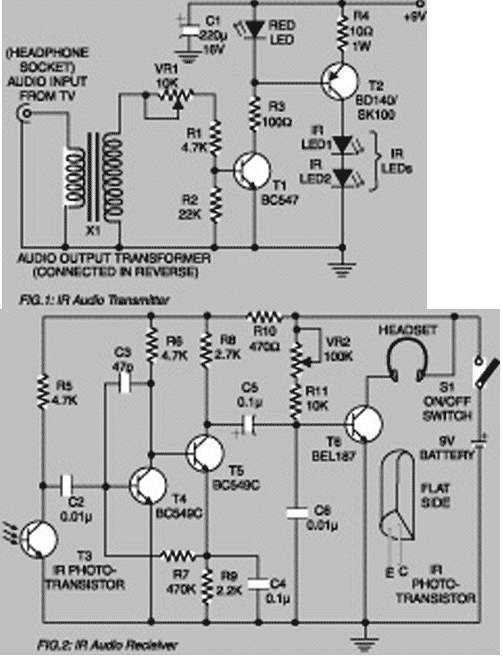
Using this low-cost project one can reproduce audio from TV without disturbing others. It does not use any wire connection between TV and headphones. In place of a pair of wires, it uses invisible infrared light to transmit audio...
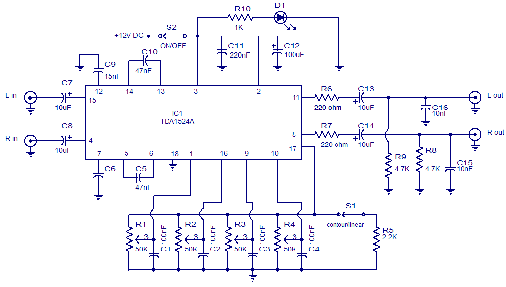
The following circuit illustrates the TDA1524 IC Stereo Preamplifier Circuit Diagram. Features include the ability to control volume, balance, and bass. The TDA1524 is a highly integrated stereo preamplifier IC designed for audio applications. This circuit configuration allows for the...
The sound system features a de-sensitized design with a maximum range that can be increased if desired. It includes two tone controls: one offering a lift of 10 dB and the other providing a subtle cut of 3 dB....

The meter utilizes time averaging to generate a direct current that is proportional to the frequency of the input signal. The described meter operates on the principle of time averaging, which is a method used in electronic measurement systems to...
The LM358 series consists of two independent, high-gain, internally frequency-compensated operational amplifiers designed specifically to operate from a single power supply over a wide range of voltages. Operation from split power supplies is also possible, and the low power...
A program is needed to set the channels to their maximum level or to write the full scale to the Digital-to-Analog Converter (DAC). The MD schematics indicate that the audio signals are mixed with ratios of 0.0431 for the...