
TDA1524 IC Stereo Preamplifier
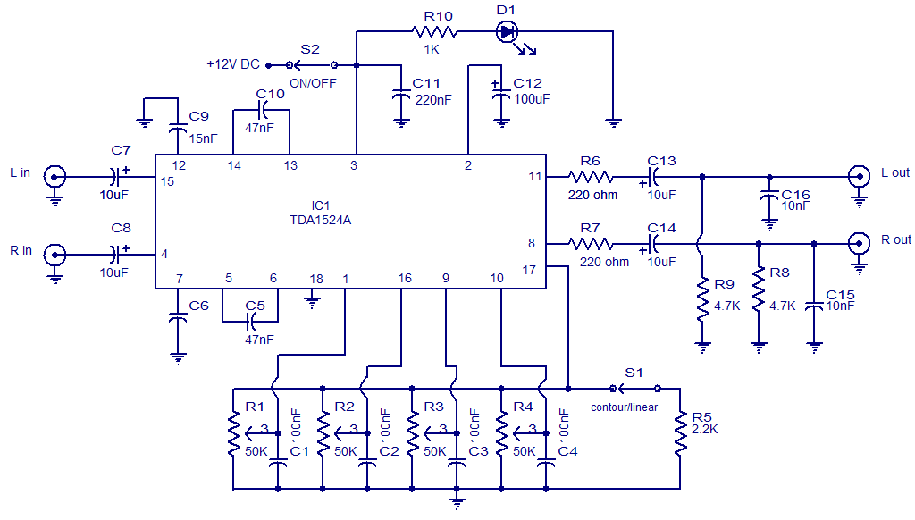
The TDA1524 is a highly integrated stereo preamplifier IC designed for audio applications. This circuit configuration allows for the manipulation of various audio parameters, including volume, balance, and bass levels, making it suitable for high-fidelity audio systems.
The TDA1524 operates with a dual power supply, typically ranging from ±9V to ±15V, ensuring sufficient headroom for audio signal processing. The IC incorporates multiple control pins that interface with external potentiometers or digital control systems, allowing users to adjust audio settings seamlessly.
The volume control is achieved through a variable resistor connected to the appropriate pin on the TDA1524, which adjusts the gain of the audio signal. The balance control is implemented using a similar variable resistor setup, enabling users to adjust the relative levels of the left and right audio channels. The bass control feature is typically realized through a low-frequency equalization circuit, which may include capacitors and resistors configured to shape the audio frequency response.
The output of the TDA1524 can be connected directly to power amplifiers or further processing stages in an audio system. Proper grounding and decoupling capacitors are essential to minimize noise and ensure stable operation. The circuit diagram should also include bypass capacitors close to the power supply pins of the TDA1524 to filter out high-frequency noise.
Overall, the TDA1524 stereo preamplifier circuit is an effective solution for enhancing audio quality and providing user-friendly control over sound characteristics in various audio applications.The following circuit shows about TDA1524 IC Stereo Preamplifier Circuit Diagram. Features: used for controlling the (volume, balance, bass and .. 🔗 External reference
Related Circuits
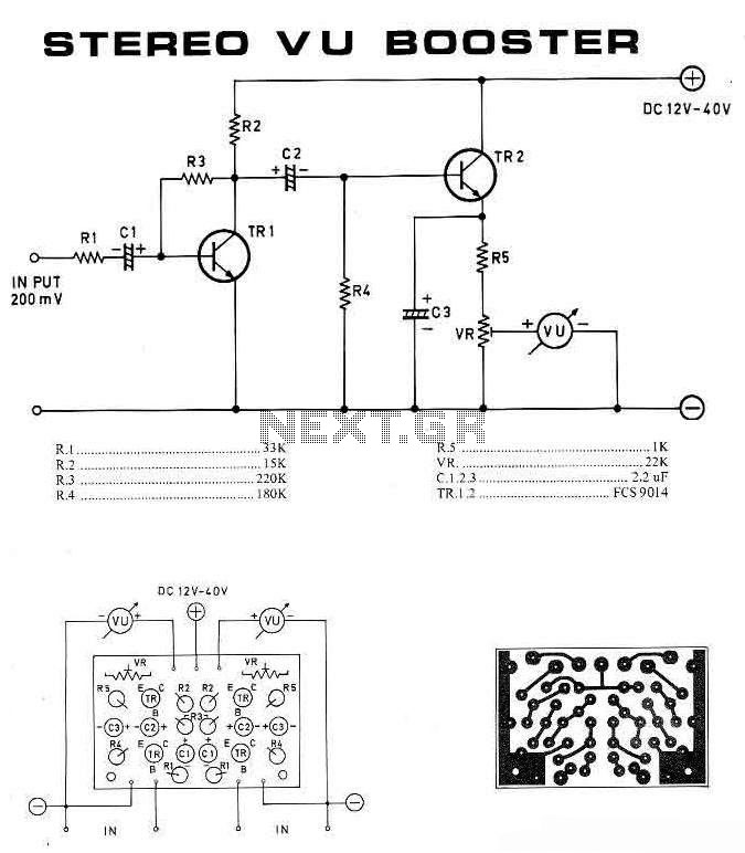
This is a stereo VU booster circuit diagram based on the transistor FCS9014, which is commonly used for pre-amplifier and regulator circuits. This circuit should be connected to the audio channel before the amplifier module. If tone control or...
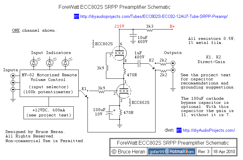
The project involves a shunt-regulated push-pull (SRPP) driver stage. Research and modeling have been conducted on the SRPP, highlighting its advantages, which include good linearity, low distortion, low output impedance, effective power supply noise rejection, and moderate gain. The...
This is a simple microphone preamplifier circuit which you can use between your microphone and stereo amplifier. This circuit amplifier microphone suitable for use with normal home stereo amplifier line/CD/aux/tape inputs. This mic preamp can take both dynamic and...
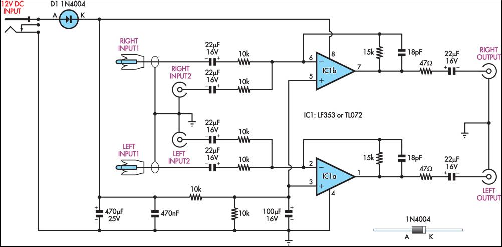
This circuit combines two separate line-level stereo (L & R) signals into one stereo (L & R) output, eliminating the need to switch between two pairs of input signals. It is utilized in a scenario where the stereo audio...
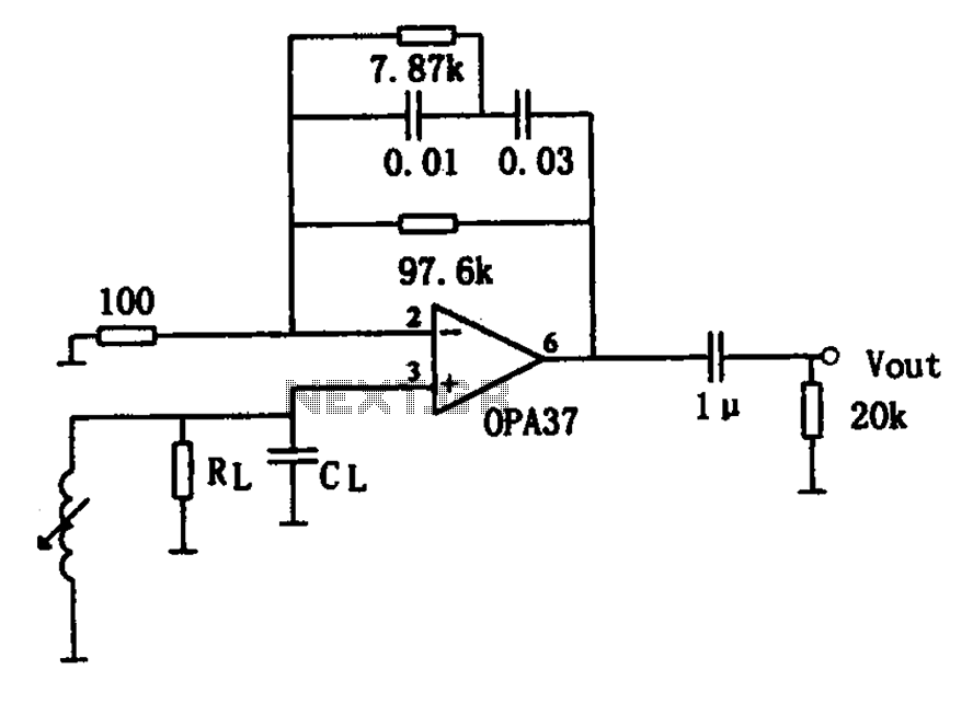
The OPA37 serves as a low-noise preamplifier. The input signal is connected to the inverting input of the OPA37 (pin 3), while the circuit components RL and CL represent the load impedance for electromagnetic pickups. The resistance and capacitance...
When the start switch is pushed, the output of the charger goes to 14.5 V. As the battery approaches full charge, the charging current decreases and the output voltage is reduced from 14.5V to about 12.5V, terminating the charging...