
Class AB Power Amplifier Circuit 30w Using Power Transistor
The 30W Class AB power amplifier is designed to provide high fidelity audio amplification with good efficiency. The circuit primarily consists of power transistors, which operate in a linear region to minimize distortion during audio signal amplification. The variable resistors R1 and R12 play crucial roles in setting the output offset voltage and quiescent current, respectively.
R1 is adjusted to control the output offset voltage, ensuring that the amplifier operates within the specified range of 30mV to 100mV. This adjustment is critical as it allows for proper biasing of the output stage, which is essential for linear operation and to prevent crossover distortion.
R12 is used to set the quiescent current, which is the idle current flowing through the output transistors when no input signal is present. A quiescent current of around 120mA is recommended to balance performance and thermal stability. As the amplifier operates, it generates heat, which can affect the quiescent current. Therefore, continuous monitoring is necessary to maintain optimal performance.
The thermal management of the amplifier is also vital. Heatsinks with a thermal resistance of 0.6K/W or lower are recommended for two amplifiers to ensure that the transistors remain within their safe operating temperatures. This is crucial for maintaining reliability and longevity in the amplifier's performance. Proper heatsinking will dissipate the heat generated during operation, preventing thermal runaway conditions that could lead to failure of the output devices.
Overall, careful setup and adjustment of the variable resistors, along with effective thermal management, are essential for the successful operation of the 30W Class AB power amplifier.30W Class AB power amplifier circuit diagram using power transistor. Set the above amplifier up by adjust the variable resistor R1 to maximum and R12 to zero. After this set up is done, the activate / turn on the amplifier. Adjust the R1 so that the measured output offset is between 30 and 100mV. Once set, adjust the R12 slowly to achieve a quiesc ent current of around 120mA. Keep checking the quiescent current as the amplifier heats up as it might change due to voltage drop changes in the output devices because of the heat. The heatsinks should be 0. 6K/W or less for two amplifiers. 🔗 External reference
Related Circuits
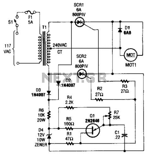
The speed-control switch provides effective control and stability across its entire operating range. This circuit utilizes two SCR devices arranged in a full-wave configuration to manage the DC power supplied to a motor. A center-tapped transformer is employed to...
The circuit is capable of measuring frequencies ranging from 1.5 kHz to 500 kHz by connecting different capacitors, C1 to C6. It can handle a maximum frequency of up to 1 MHz. Transistor T1 serves as the integrator, with...
the AD844 was still used, but this time the feedback loop went all the way from output and back to input. The DC servo was removed and the current source was made faster, using an extra transistor. The local...
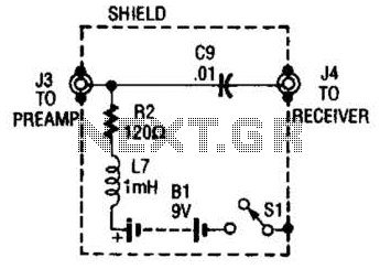
The purpose of the receiver/interface circuit is to pass RF to the receiver through capacitor C9, while adding DC power to the feedline through resistor R2 and RF choke L7. The receiver/interface circuit is designed to facilitate the transmission of...
Simple and low cost. The optimal supply voltage is around 50V, but this amp works from 30 to 60V. The maximal input voltage is around 0.8 - 1V. As you can see, in this design the components have a...
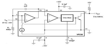
The circuit diagram of a voltage-to-frequency (V/F) converter is presented, designed to handle negative input voltage. It employs the VFC32 voltage-to-frequency converter, which is commonly utilized in various applications. The V/F converter circuit is essential in converting an analog voltage...