
Speed-Control Switch Circuit
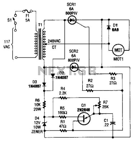
The speed-control switch circuit employs a dual SCR arrangement to facilitate the control of DC power to a motor, allowing for variable speed operation. The full-wave configuration of the SCRs enables efficient power delivery by allowing both halves of the AC waveform to be utilized, thereby improving the overall efficiency of the motor control system.
The circuit begins with a center-tapped transformer that provides the necessary AC voltage. The center tap serves as a neutral point, allowing the two SCRs to be triggered alternately, thus controlling the average voltage and current supplied to the motor. This method of control is advantageous as it minimizes power losses compared to other control methods, such as resistive control.
The SCRs are triggered into conduction by a gate signal, which can be modulated to adjust the firing angle of the SCRs. By varying the firing angle, the effective voltage applied to the motor can be controlled, resulting in variable speed operation. This provides the user with the ability to finely tune the motor speed according to specific operational requirements.
In addition to the SCRs and transformer, the circuit may include additional components such as diodes for flyback protection, capacitors for filtering, and resistors for biasing and limiting current. Proper heat dissipation methods must also be considered, as SCRs can generate significant heat during operation.
Overall, this speed-control switch circuit is an effective solution for applications requiring precise control of motor speed, combining simplicity with robust performance. The speed-control switch offers reasonably good control and stability to both ends of its operating range. This circuit uses two SCR devices in a full-wave configuration to control the dc power to a motor. A center-tapped transformer is used to supply the SCRs. 🔗 External reference
Related Circuits
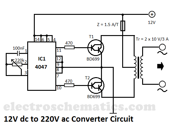
This DIY 12V to 220V voltage converter is built with the CMOS 4047, which serves as the main component of this compact voltage converter that transforms 12V DC into 220V AC. The 4047 is configured as an astable multivibrator,...
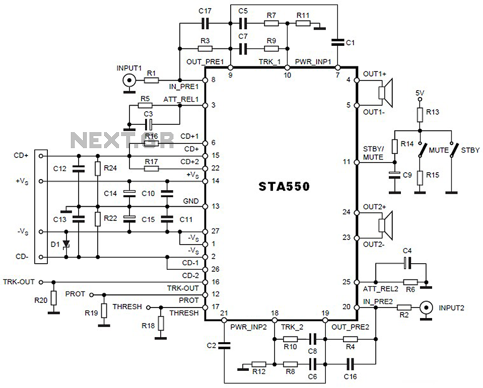
This is a 2 x 70W audio power amplifier circuit built using a single IC STA550. The amplifier circuit requires a few external components, primarily resistors and capacitors, and is straightforward to design. The STA550 audio amplifier can provide...
Chris from PyroElectro.com has an informative article detailing a do-it-yourself radar system constructed using the PIC18F452 microcontroller. This project is an excellent hobbyist endeavor, although the schematic design is quite complex. The system integrates three primary components to form...

The BFP640 transistor is utilized for 1575 MHz Global Positioning Satellite (GPS) applications, specifically as a Low Noise Amplifier (LNA). The design objectives include a minimum gain of 16 dB, a noise figure of less than 0.6 dB, an...
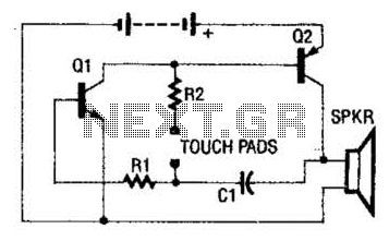
The circuit employs a two-transistor direct-coupled oscillator, with its frequency determined by capacitor C1, resistor R2, and the skin resistance across the touch pads. Since C1 and R2 are fixed values, only the skin resistance can vary the sound...
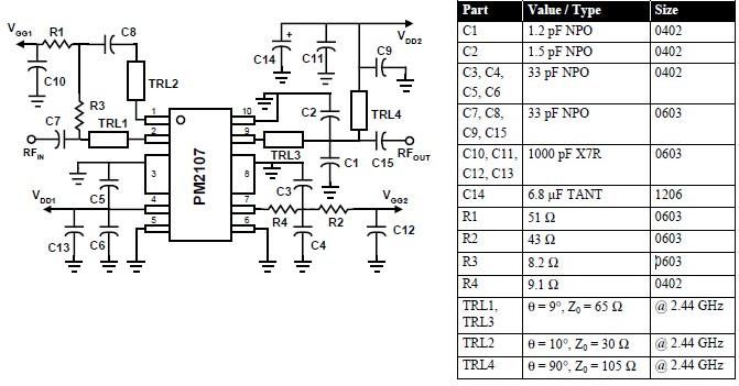
This RFIC amplifier operates in the 2400 MHz ISM band and features a two-stage design that is off-chip matched to ensure optimal performance across various applications. Powered by a 5-volt supply, the PM2107 can deliver 1 watt of saturated...