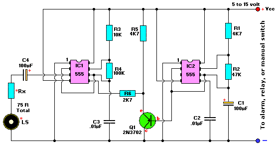
Motorcycle or car alarm

The trembler (motion-activated) switch triggers an alarm for 5 seconds before automatically turning off. The circuit has a timeout period of 10 seconds to allow the trembler switch to stabilize.
The trembler switch circuit operates by detecting motion through a mechanical or electronic sensor, which activates an alarm for a predetermined duration. Upon detection of motion, the circuit initiates an alarm signal that lasts for 5 seconds, providing an audible alert. Following this alarm period, the circuit automatically deactivates the alarm, ensuring it does not remain active indefinitely.
To accommodate the operation of the trembler switch, a timeout mechanism is integrated into the circuit design. This timeout period lasts for 10 seconds, during which the circuit allows the trembler switch to settle and return to its original state. This feature is particularly important in preventing false alarms caused by minor disturbances or vibrations that may occur immediately after the initial motion detection.
The circuit typically consists of a motion sensor, a timer, and an alarm output device. The motion sensor can be implemented using various technologies, such as passive infrared (PIR) sensors or mechanical tilt switches, depending on the application requirements. The timer can be realized using a simple RC (resistor-capacitor) network or a more sophisticated microcontroller, depending on the desired accuracy and complexity.
In summary, the trembler switch circuit is designed to provide a reliable motion detection and alarm system with built-in stabilization to minimize false alarms, making it suitable for various applications, including security systems and automated alert mechanisms.Trembler (motion activated) switch sounds the alarm for 5 seconds. Then it goes off Circuit is timed out for 10 seconds to allow the trembler switch to settle. 🔗 External reference


