
Clock pulse generator for CMOS

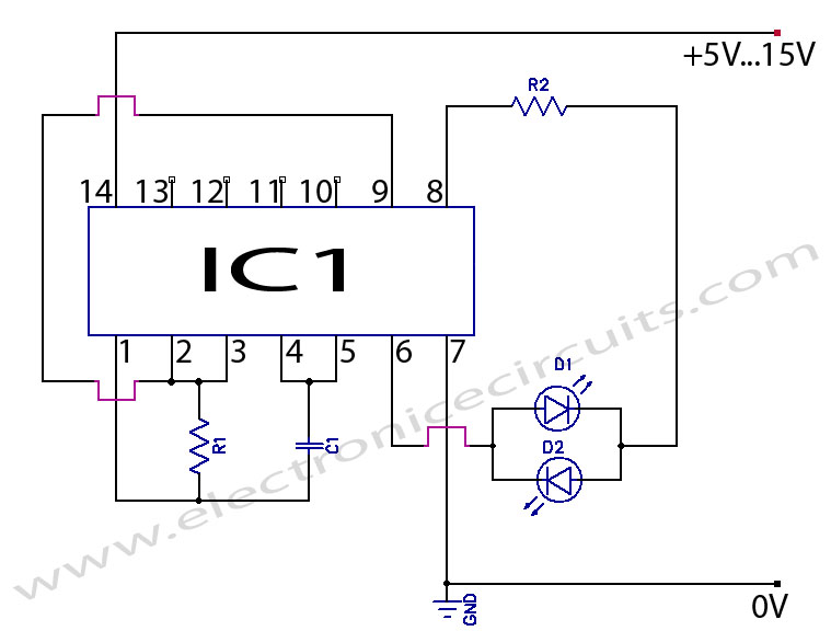
The described clock generator circuit is designed to provide a stable clock signal for driving CMOS circuits, specifically the CD4017 decade counter. The circuit utilizes a resistor (R1) and a capacitor (C1) to establish the oscillation frequency, which is crucial for the operation of the connected CMOS devices.
The resistor R1 can be selected between 10K ohms to 10M ohms, allowing for flexibility in tuning the frequency of the generated clock signal. The capacitor C1 can be chosen from a range of 100 picofarads (pF) to 47 microfarads (μF), which also directly influences the timing characteristics of the oscillator. The relationship between R1, C1, and the output frequency (Fo) of the generator is such that when R1 is set to 100K ohms and C1 to 10nF, the output frequency is approximately ±1KHz.
The input voltage range for this clock generator is specified from 5V to 15V, which accommodates a variety of power supply options, making the circuit versatile for different applications. The design is likely based on a simple astable multivibrator configuration, possibly utilizing a 555 timer IC or a similar oscillator circuit, which provides a square wave output.
In practical applications, this clock generator can be used not only with the CD4017 but also with other CMOS logic devices that require a clock input for synchronous operation. The ability to adjust the frequency makes it suitable for various timing applications, including LED flashing, frequency division, and other timing-related tasks in electronic projects. Proper selection of R1 and C1 values is essential to achieve the desired frequency and stability in the output signal.Excellent clock generator to drive 4017 type cmos circuits. R1 = 10K to 10M, C1 = 100pF to 47uF. Fo is ±1Kz when R1=100K and C1=10nF. Input voltage can be from 5 to 15V. 🔗 External reference
Related Circuits
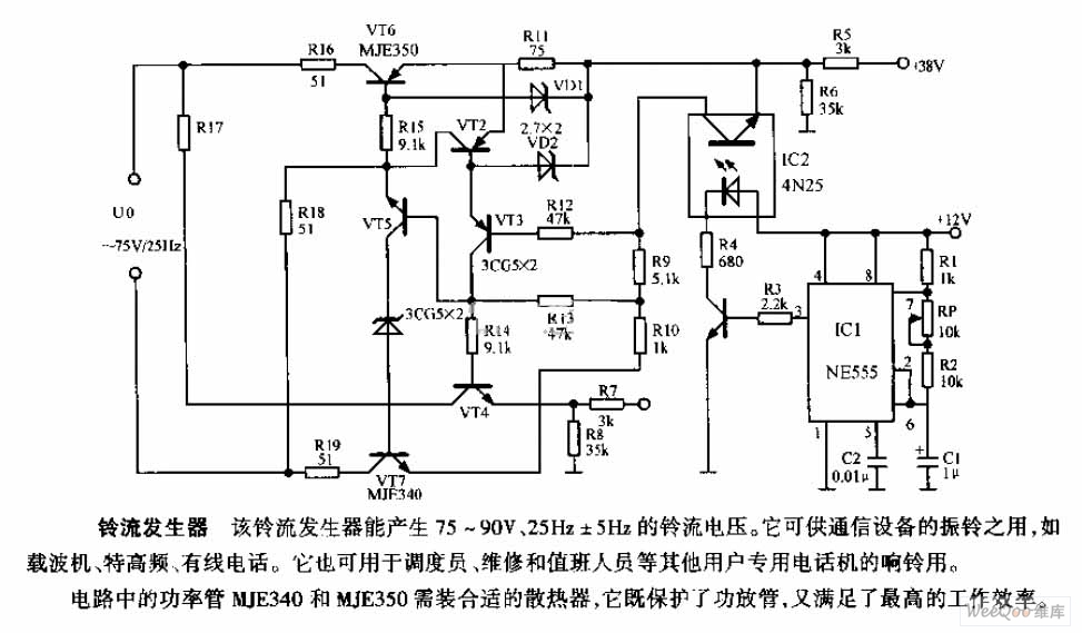
The ring current generator can produce a ringing current voltage of 75-90V and 25Hz ± 5Hz. It is suitable for use in vibrating rings in communication devices, such as carriers, ultrahigh frequency systems, and wire telephones. Additionally, it can...
Two LED CMOS Flasher Circuit Diagram. This is a simple two LED CMOS robot (flasher, multivibrator) circuit using CD4069 six inverters. The two LED CMOS flasher circuit utilizes the CD4069 integrated circuit, which contains six inverters, to create a multivibrator...
This precise one-pulse-per-second clock is constructed using a few common components and is driven by a 50 or 60 Hertz mains supply without a direct connection to it. An audible beep or a metronome-like click, along with a visible...
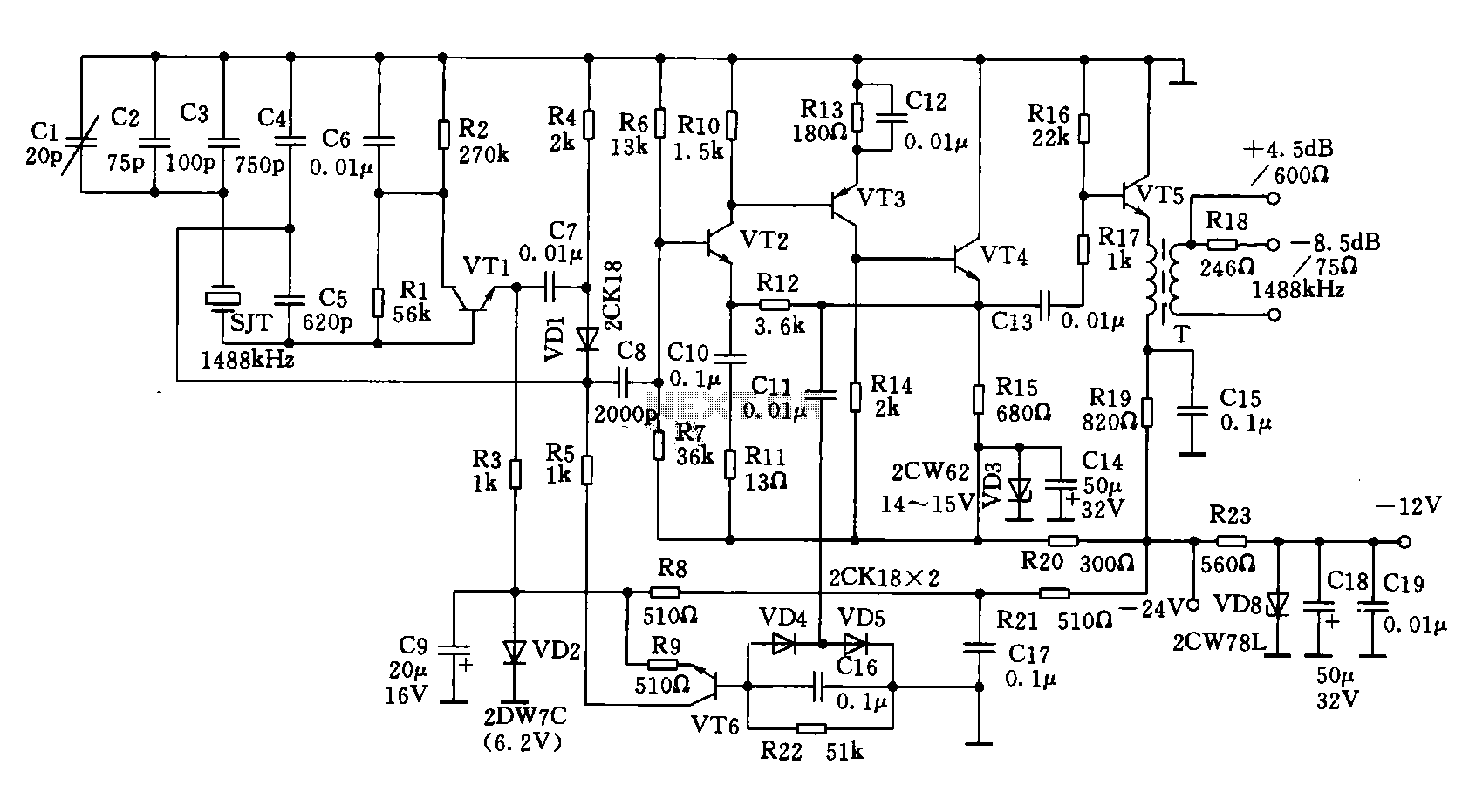
A 1488 kHz master oscillator quartz crystal resonator is utilized for frequency stabilization. The output from the frequency divider provides three different square wave signal outputs at 4 kHz, 12 kHz, and 124 kHz. The circuit includes transistors VT1,...
The control of electric motors is a topic of interest for those involved in Meccano model building. Each model has specific motor requirements concerning available space, motor power, speed, frequency of start and stop, and the necessity for reduction...
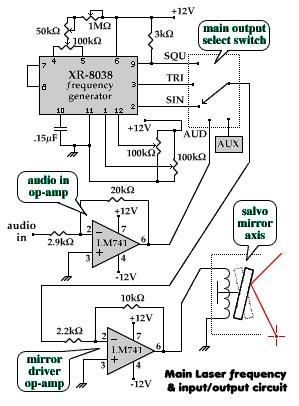
The aim of this project is to visually demonstrate the interactions of frequencies with one another. By utilizing mirrors and magnets to reflect a laser beam, a visual representation of the mathematical principles inherent in electronics is created. The...