
one second audible clock circuit schematic
The one-pulse-per-second clock circuit is designed to provide an accurate timing signal that can be used in a variety of applications, including timers, clocks, and metronomes. The circuit leverages the CMOS 4024 counter/divider chip, which is capable of dividing down the frequency of an input signal to achieve the desired output frequency.
The operational principle involves feeding a stable 50 or 60 Hertz signal into pin #1 of the CMOS 4024. The chip is configured to divide this input frequency by a factor of 50 or 60, depending on the mains frequency in the region of use. This division results in a clean one-pulse-per-second output, which can be accessed from one of the output pins of the CMOS 4024.
In addition to the counter chip, the circuit includes three diodes that serve to rectify and shape the input signal, ensuring that the CMOS chip receives a clean and stable waveform. This configuration helps to prevent any potential noise or fluctuations in the mains supply from affecting the timing accuracy of the output signal.
The output pulse can be utilized to drive a speaker or buzzer for an audible indication, or it can be connected to an LED for a visual cue. The combination of both audio and visual signals enhances the usability of the clock circuit in various applications, making it suitable for educational tools, timing devices, and other electronic projects where precise timing is essential.
Overall, this one-pulse-per-second clock circuit is a simple yet effective solution for generating accurate timing signals, leveraging commonly available electronic components to achieve reliable performance.This accurate one-pulse-per-second clock is made with a few common parts and driven from a 50 or 60 Hertz mains supply but with no direct connection to it. A beep or metronome-like click and/or a visible flash, will beat the one-second time and can be useful in many applications in which some sort of time-delay counting in seconds is desirable.
The circuit is formed by a CMos 4024 counter/divider chip and 3 diodes, arranged to divide the frequency of the input signal at pin #1 by 50 (or 60, see Notes).. 🔗 External reference
Related Circuits
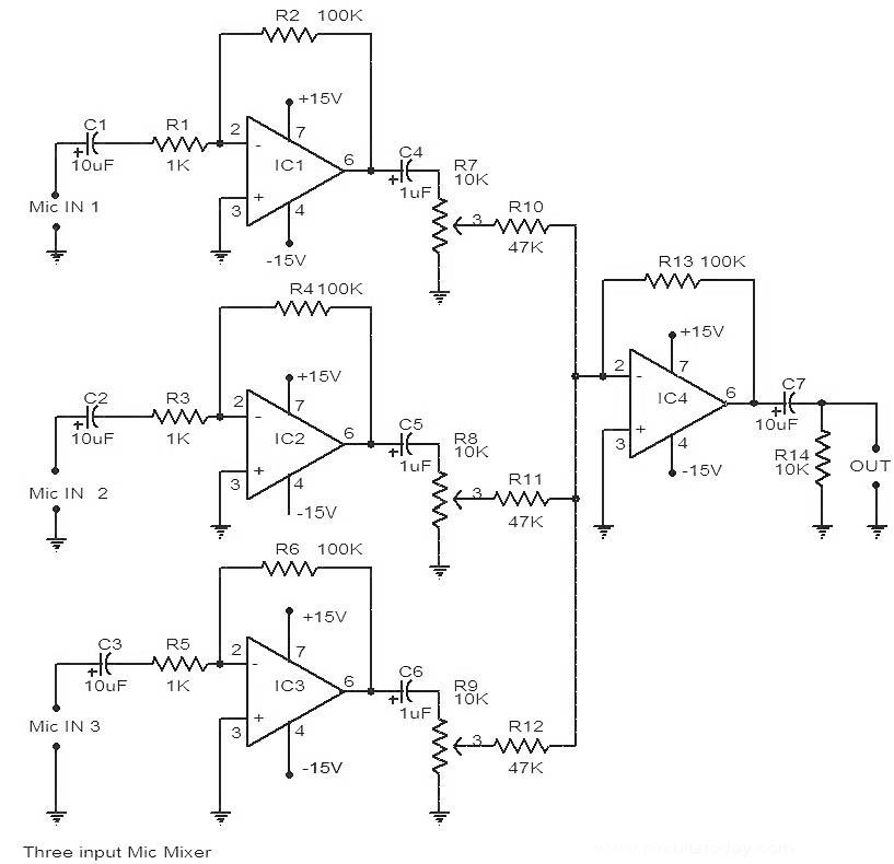
This is a circuit diagram of a 741 IC-based three-input microphone mixer circuit. A total of four 741 ICs are utilized, with IC1, IC2, and IC3 serving specific functions within the design. The circuit utilizes four operational amplifiers from the...
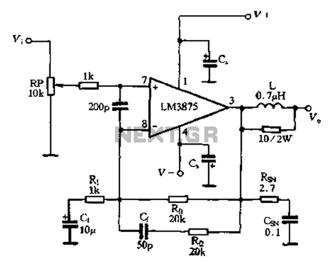
The 875T and LM3876T are high-performance 40W power amplifier integrated circuits (ICs). They operate within a frequency range of 20Hz to 20kHz with a continuous average power output under an 8-ohm load and exhibit a distortion level of only...
Some relays will become warm if they remain energized for some time. The circuit shown here will actuate the relay as before but then reduce the hold current through the relay coil by about 50%, thus considerably reducing the...
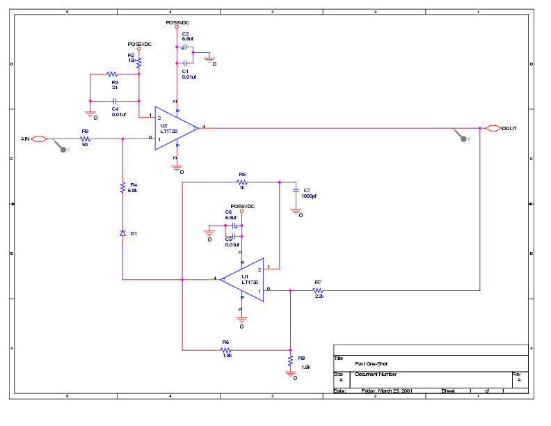
This circuit is from the datasheet for Linear Technology's LT1720, a 4.5 ns comparator. It is labeled "Pulse Stretcher" at the end of the document. Essentially, it functions as a one-shot with sensitivity down to 14 mV for input...
This article explains how to construct a general-purpose DTMF decoder using an affordable chip from MITEL. The circuit supports DTMF squelch based on a three-digit station ID (covering all 999 combinations). It can also decode four additional commands, which...
A basic digital voltmeter circuit utilizing the Harris Semiconductor ICL7107 is presented. It operates within a 2-V range. Calibration involves applying a known voltage of 1.2 V to the input and adjusting resistor R3 to achieve an accurate reading...