
Clock source
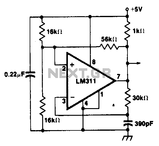
The proposed circuit utilizes the LM311 voltage comparator configured in a positive feedback arrangement to generate a stable clock signal. The LM311 is a high-speed voltage comparator that can operate with a wide range of supply voltages, making it suitable for various applications requiring precise timing signals.
In this configuration, the output of the LM311 is fed back to its non-inverting input through a resistor network, creating a hysteresis effect. This feedback loop helps to stabilize the output frequency and reduces the susceptibility to variations in supply voltage or temperature, which can lead to frequency shifts. The resistor values can be selected to define the threshold levels for the input signal, thus controlling the frequency of oscillation.
To further enhance the performance of the clock source, a capacitor can be added in parallel with the feedback resistor. This capacitor introduces a time delay, which can be adjusted to fine-tune the oscillation frequency. The combination of the resistor and capacitor forms an RC network that determines the charging and discharging time constants, directly influencing the clock period.
For practical implementation, additional components such as decoupling capacitors should be included near the power supply pins of the LM311 to ensure stable operation. Furthermore, output buffering may be necessary if the clock signal is to drive other digital circuits, ensuring that the load does not affect the performance of the clock source.
Overall, this circuit design provides a reliable and efficient method for generating clock signals, suitable for various digital applications, including timers, pulse generators, and clock sources for microcontrollers.A clock source using LM311 voltage comparator in positive feedback mode to minimize clock frequency shift problem. 🔗 External reference
Related Circuits
In the circuit below, 60 individual LEDs are used to indicate the minutes of a clock and 12 LEDs indicate hours. The power supply and time base circuitry is the same as described in the 28 LED clock circuit...
To initiate the process in 24 seconds, the LOAD switch and Reset switch must be pressed simultaneously. If this action is not performed, the countdown will commence from 99. A pulse input can be connected to a 555 astable...
This precise one-pulse-per-second clock is constructed using a few common components and is powered by a 50 or 60 Hertz mains supply without any direct connection to it. A beep or metronome-like click, along with a visible flash, indicates...
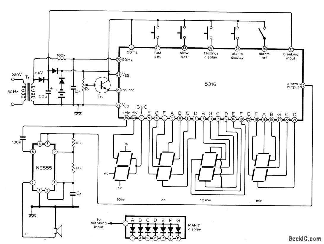
The circuit utilizes the MM5316 alarm-clock integrated circuit (IC), which is originally intended for driving LCD or fluorescent displays. In this implementation, it has been adapted for use with LED display diodes. The system is designed to operate on...
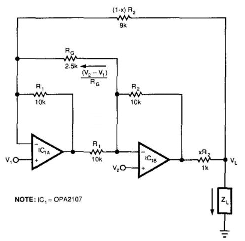
This circuit responds to the difference between Vj and V2. Rq sets the gain. Resistors XR2 and (1 - X) R2 produce the bootstrap effect. These two resistors convert the circuit's output voltage to a current. IC1 and IC2...
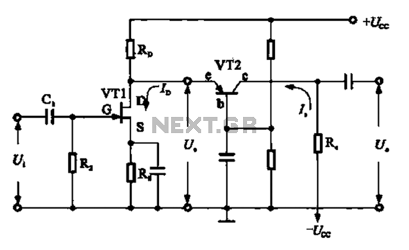
A combination of a common-source grounded base amplifier formed by cascaded amplifiers. The source is grounded, and a common base amplifier is combined into a cascaded amplifier. The graph below shows the low noise characteristics of the FET common-base...