
Closed-Loop Automatic Power Control for RF Applications

The Closed-Loop Automatic Power Control (APC) circuit is designed to maintain a consistent output power level in RF applications, such as transmitters and amplifiers. The system operates by continuously measuring the output power using the log detector AD8318, which provides a logarithmic representation of the input power level. This feature allows for a wide dynamic range and precise power level detection, making it suitable for applications where power fluctuations can significantly impact performance.
The output from the AD8318 is fed into the variable gain amplifier (VGA) ADL5330, which adjusts the gain based on the detected power level. By varying the gain, the VGA can compensate for any changes in output power, ensuring that the desired output level is maintained. The feedback loop formed by the log detector and the VGA allows for rapid adjustments in response to changes in the input signal, providing stable operation under varying conditions.
In terms of implementation, the circuit typically includes additional components such as resistors and capacitors to filter and stabilize the signals. Proper layout and design considerations are crucial to minimize noise and ensure reliable operation, particularly in high-frequency applications. The power supply for the components should also be carefully regulated to avoid introducing additional variations in the output power.
Overall, this closed-loop APC circuit is essential for achieving optimal performance in RF systems, allowing for efficient power management and improved signal integrity.This is a circuit of Closed-Loop Automatic Power Control for RF Applications. The circuit uses a log detector (AD8318) and a VGA (ADL5330). This circuit has a. 🔗 External reference
Related Circuits
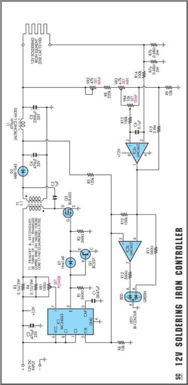
One reason why commercial soldering stations are expensive is that they typically require soldering irons with built-in temperature sensors. Commercial soldering stations are designed to provide precise temperature control and consistency during soldering operations, which is essential for achieving reliable...
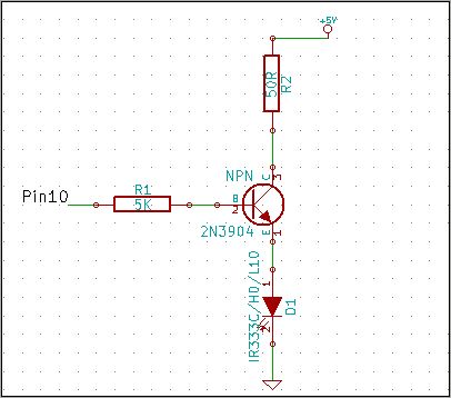
The 2N3904 is an NPN transistor. When observing the flat face of the transistor, the left lead is the Emitter (pin 1 in the schematic), the middle lead is the Base (pin 2 in the schematic), and the right...
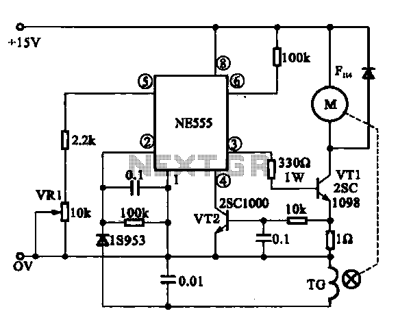
The Miniature DC Motor Speed Control circuit is designed to maintain a steady speed for micro motors, as illustrated in Figure 8-32. The circuit utilizes a voltage feedback mechanism suitable for applications such as tape recording machines that employ...
The 555 is wired as an astable and the capacitor is charged only through the 4.7Kohm trimmer (notice the diode) and discharged only through the 2.2 Kohm trimmer, making the duty cycle fully adjustable. The square wave is then...
The MAX1846 inverting circuit implements a switch-mode power supply that provides -15V at 0.5A output from a 4.5V to 12V input. This circuit incorporates additional components beyond the minimum implementation. C20 introduces a pole to compensate for the ESR-zero...
Modern ICON electronic engine controls from BRP The ICON electronic engine control system developed by Bombardier Recreational Products (BRP) represents a significant advancement in marine technology. This system integrates sophisticated electronic controls to enhance the performance and reliability of marine...