
Miniature DC Motor Speed Control circuit
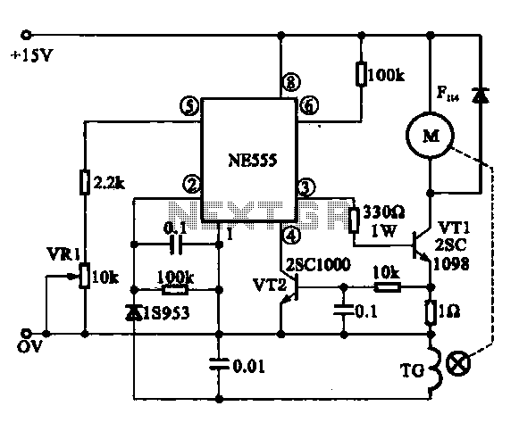
The Miniature DC Motor Speed Control circuit operates by employing a combination of feedback mechanisms and control components to ensure consistent motor performance. The NE 555 timer serves as the central control unit, functioning in astable or monostable mode depending on the application requirements. In this configuration, the timer generates a series of pulses that dictate the switching of the transistor VT1, which in turn energizes the motor.
The feedback loop is critical for maintaining the desired speed. The voltage feedback from the motor is processed by the NE 555 timer, which compares the actual motor speed to the setpoint defined by the potentiometer VR1. By fine-tuning VR1, the user can adjust the threshold at which the NE 555 timer activates the transistor, thereby increasing or decreasing the motor speed as needed.
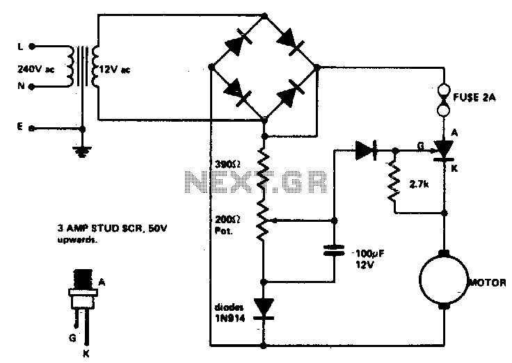
In the case of the speed feedback motor drive circuit depicted in Figure (b), the integration of a speed signal generator (TG) enhances the control mechanism. The TG outputs a signal that corresponds to the actual speed of the motor. This signal is rectified and converted to a DC voltage, which provides real-time feedback to the NE 555 timer. The timer continuously monitors this feedback and adjusts its output accordingly to ensure that the motor operates at a steady speed, compensating for any variations in load or supply voltage.
Overall, this circuit design is particularly useful in applications where precise speed control of miniature DC motors is essential, offering both simplicity and effectiveness in maintaining operational stability.Miniature DC Motor Speed Control circuit b Having a steady speed function micro motor drive circuit steady speed Miniature DC motor control circuit shown in Figure 8-32. Ring (a) shows the voltage feedback mode is for tape recording machine miniature DC motor drive circuit, which uses NE 555 when the base integrated circuit VT1 transistor output switching pulses through the drive motor rotation turn. NE 555 feet for the negative feedback signal input. Through the feedback loop to achieve steady speed control, feet external potentiometer VR1, can speed into fine adjustment.
Figure (b) shows the use of speed feedback motor drive circuit, which is provided to the motor speed signal generator TG, a speed signal filtered by the rectifier into a DC voltage is fed back to the @ NE 555 feet, the NE 555 testing and comparison, then by foot output a variable control signal, so as to achieve the purpose of steady speed.
Related Circuits
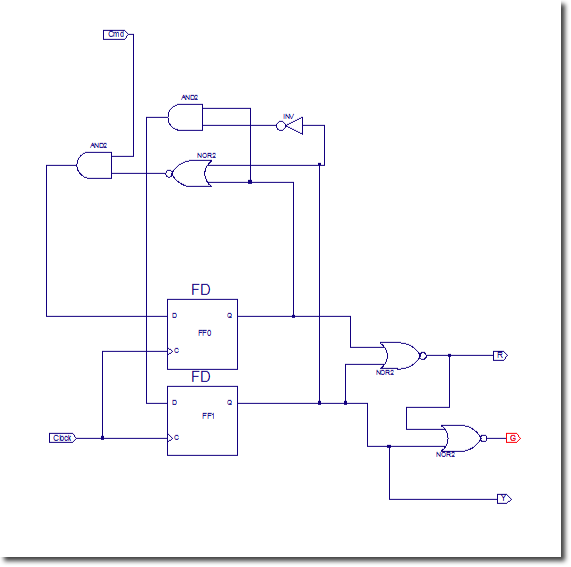
In this lab, flip-flops will be utilized. Xilinx provides a comprehensive library of sequential circuits, which is recommended for circuit searches: Xilinx Reference Library. The objective of this lab is to implement a sequential circuit that controls three LEDs:...
An advantage of a photogate over a sound trigger is that the former activates based on the exact position of the object that interrupts the beam. For instance, the shape of a snapped elastic cord can be captured as...
Low voltage speed control provides excellent starting torque and effective speed regulation. Additionally, a reversing switch can be integrated into the motor leads. Low voltage speed control circuits are essential in applications where precise motor control is required, such as...
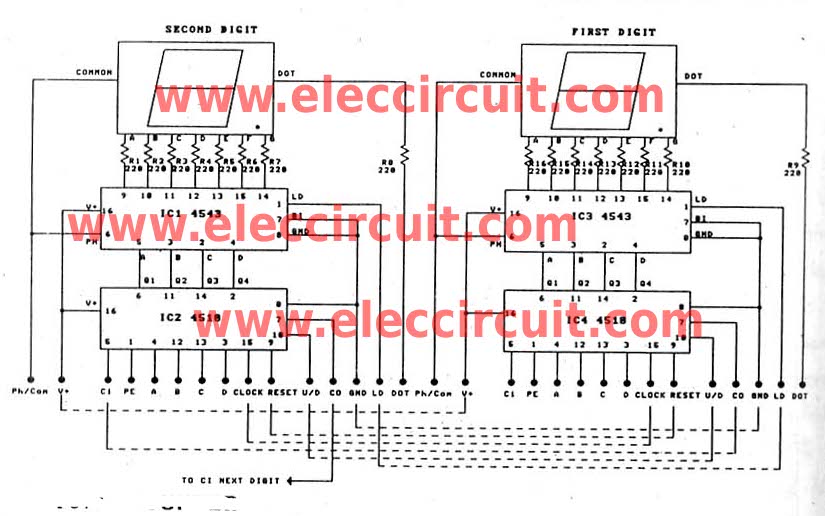
This is a versatile digital counter circuit that is cost-effective due to the basic components available in many electronic shops. The digital counter circuit is designed to count pulses and display the count on a digital readout, typically using a...
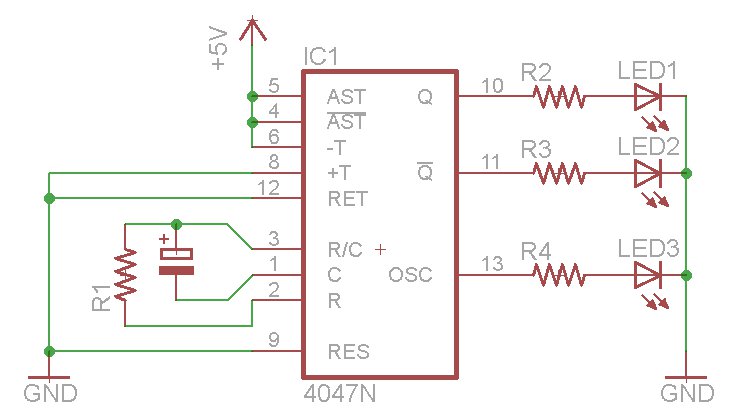
The oscillator output generates a signal that is approximately twice the frequency of Q. The other pins will be considered subsequently. In a brief video demonstration, LEDs are connected to all three outputs, illustrating the alternating behavior of Q...
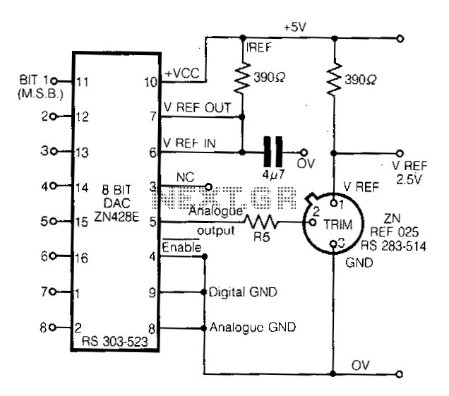
This circuit demonstrates a straightforward approach to achieving a voltage reference that can be adjusted using an 8-bit Digital-to-Analog Converter (DAC) equipped with an integrated voltage reference. The analog output from the DAC controls the trim pin of the...