
CM2 Practical
The circuit employs a 7555 timer configured in astable mode to generate a square wave signal. This timer is critical for establishing the timing characteristics of the circuit. The output from the timer feeds into the RC4200 single quadrant multiplier, which processes the square wave to achieve the desired amplitude modulation. The two-quadrant square root circuit is essential for transforming the input voltage into a corresponding output voltage, enabling precise control over the signal characteristics.
The comparators serve as limit detectors, providing feedback through LED indicators that visually represent when the input signal approaches specified thresholds. This feedback mechanism is crucial for maintaining signal integrity and preventing distortion during operation. The amplifier stage, with its gain of 20, is designed to handle the amplified output without introducing excessive noise or distortion, ensuring that the high voltage output remains stable and reliable.
The push-pull oscillator design is advantageous for applications requiring low output impedance, allowing for efficient signal amplification without significant losses. The regulated power supply ensures that fluctuations in the input voltage do not adversely affect the output signal. The galvanic isolation provided by the transformer is a critical feature for maintaining measurement accuracy, particularly when dealing with high voltages.
The diamond transistor configuration facilitates accurate current measurements by ensuring that the output current remains consistent regardless of voltage variations. The inclusion of a switchable capacitance allows for adaptability in sensitivity, accommodating a range of applications.
The synchronous rectifier and low-pass filter work in tandem to demodulate the signal, producing a clean output ready for further amplification. The design considerations regarding frequency splitting are essential for minimizing crosstalk and ensuring that the integrity of the measurement circuit is preserved.
Overall, the circuit is designed with careful consideration of component selection, signal processing techniques, and feedback mechanisms, resulting in a robust system capable of handling high-voltage measurements with precision.The square wave is generated by a 7555 timer operating with a supply of 10V and thus generating exactly this voltage as output voltage. With the single quadrant multiplier (RC4200, Fairchild, obsolete) the two quadrant square root circuit is formed.
10V of input voltage is converted to 10V output exactly (2. 5V to5V, 1V to 3. 16V, 0. 1V to 1V etc. ). The signal is limited to a lower limit of 0V and a switchable limit of 2. 5, 5, 0. 75 or 10V. Two comparators and associated LEDs indicate when the limits are reached. It turned out to be helpful to adjust the input signal to a maximum amplitude (lin or sqrt) by just observing these LEDs. This amplifier has a gain of 20 so that the nominal input voltage of 10V becomes 200V. The full power bandwidth with an output load of 300pF is 400kHz approx. and thus sufficient for all important harmonics when the square root of a 20kHz AF-signal has to be amplified to 200Vpp.
The output is current limited to a few mA and short circuit proof. The oscillator is a sine wave push-pull oscillator. This kind of circuit has a low output impedance and generates an output amplitude which is quite exactly depending on the supply voltage only. This makes the circuit nicely "predictable" and this is why it operates with its own regulated power supply of 8V.
Though its low output impedance it is still buffered because the measuring voltage not only has to have a low impedance, but a very low impedance so that high currents through the measured capacitor do not alter the voltage unacceptably. In order to allow the measured capacitance (capsule) to be connected to ground the measuring voltage is galvanically decoupled by a transformer which allows not only the current measuring circuit to be ground referenced too but also the introduction of a variable compensation capacitor (0 - 390pF) so that a wide range of null adjustment is possible.
Current measurement is performed ground referenced by a so-called "diamond transistor" (OPA660, Burr-Brown, obsolete). The current flowing in its low-impedance input (emitter) is reflected at the (collector) output and is independent of the voltage there.
Actually this a current controlled current source, similar to a current mirror. The output current is converted to a voltage by a switchable capacitance so that two different sensitivity ranges are available. An inductor with an XL much larger than XC is needed for a minor DC-bias current and reduces low frequency noise.
A synchronous rectifier, i. e. a multiplier (AD734, Analog Devices), detects or demodulates the signal. Its output voltage is a 4MHz sine wave and can swing between +/-5V (negative, when the variable compensation capacitor is set up accordingly high), and its mean value (DC portion) can be up to +/-2. 5V. Therefore after an AF low-pass filter an amplifier with a switchable gain of 4 or 40 is foreseen, so that in either case an output range of +/-10V is achieved.
The 2MHz measuring voltage must not arrive at the HV-amplifiers output as, due to the dynamical changes of the amplifiers output parameters, it would be influenced in phase and amplitude there and reflected back to the detector falsify measured signals there. Likewise, the high-voltage AF-signal from the HV-amplifier must not arrive at the detector circuit as due to non ideal operation, it might directly propagate trough it and falsify the results, too.
This frequency splitter turned out to be very crucial and currently is implemented by two series resonant and two parallel resonant circuits. Nevertheless, it seems that something must be improved here. It looks like the high voltage transients alter capacitive or inductive values so that there is still an unacceptable crosstalk from the HV-output through the detector to the AF-output.
The circuit is operated with an external voltage of +12V, and internal voltages of (close to) -12V and +240V are produ 🔗 External reference
Related Circuits
Currently, there is a growing trend to utilize telephone lines for long-range control and alarm systems within transmission mediums, which is accompanied by extensive research. Such systems typically consist of alarm devices and police notification arrangements, including a central...
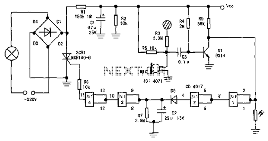
The circuit diagram illustrates a sound, light, and touch-controlled delay self-extinguishing switch. It comprises three main sections: the power circuit, the signal conversion detecting circuit, a delay circuit, and a control circuit. 1. Power Circuit: This section consists of...
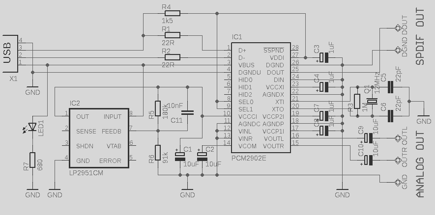
This circuit is a quality preamplifier with a built-in USB DAC designed for the Leachamp power amplifier. The schematic is based on the PCM2902 datasheet. The circuit includes a DAC and ADC, SPDIF input and output, and features three...
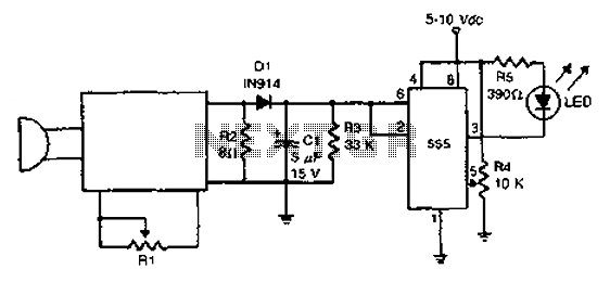
The acoustic detector consists of a Schmitt trigger IC555 connected to various components. When the input exceeds a certain voltage, the output will change state from high to low. R4 is used to set the threshold voltage. The acoustic detector...
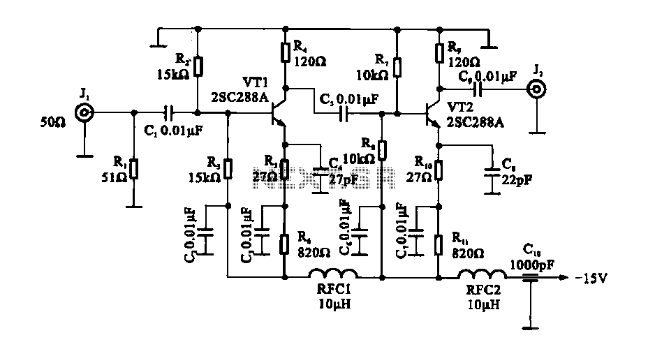
The circuit consists of a two-stage common emitter amplifier, which serves as a practical wideband amplifier. It utilizes capacitors for coupling between the input and output stages. The emitter decoupling capacitor, C4, is employed to eliminate AC negative feedback,...
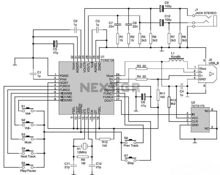
The USB Sound Card circuit is based on the PCM2706, which is designed for USB audio applications. The PCM2706 includes a USB controller module, eliminating the need for additional programming of the integrated circuit (IC). The computer system will...