
Practical sound level monitor circuit diagram

The acoustic detector circuit utilizes the Schmitt trigger configuration of the IC555, which is known for its ability to provide hysteresis in switching applications. This characteristic is particularly useful in noise-sensitive environments, allowing the circuit to avoid false triggering due to small fluctuations in the input signal.
The primary function of the circuit is to detect acoustic signals that exceed a predefined threshold voltage. The input signal is fed into the non-inverting input of the Schmitt trigger. As the input voltage rises and crosses the threshold set by the resistor R4, the output of the IC555 transitions from a high state (logic 1) to a low state (logic 0). This transition can be utilized to activate further circuitry, such as alarms, indicators, or other control systems.
R4 plays a crucial role in defining the threshold voltage, and its value can be adjusted to tailor the sensitivity of the detector to specific acoustic levels. Additional components, such as capacitors and resistors, may be included in the circuit to filter out noise and stabilize the input signal, ensuring reliable operation.
Overall, this acoustic detector circuit is effective for applications requiring sound detection, such as security systems, sound-activated switches, and various automation tasks, where the precise detection of sound levels is critical.Acoustic detector consists of a Schmitt trigger IC555 connected components. Just input exceeds a certain voltage, its output will change state, from high to low. R4 to set the threshold voltage.
Related Circuits
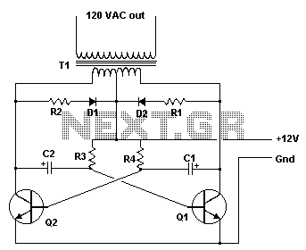
This inverter is designed to operate appliances such as TVs and stereos while traveling or camping. It converts 12 VDC to 120 VAC, with the output wattage determined by the transistors used for Q1 and Q2, as well as...
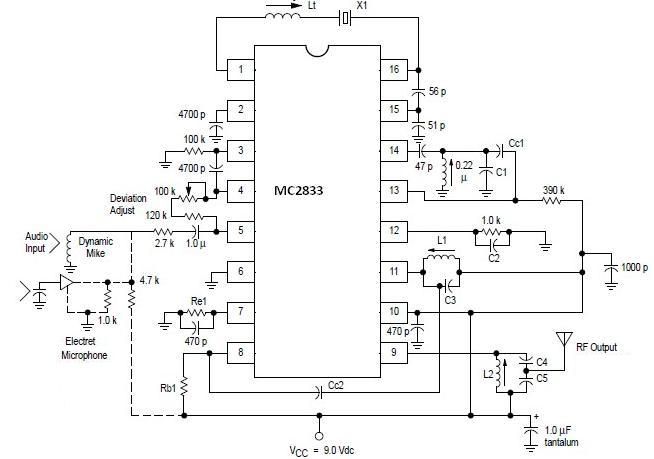
A simple FM transmitter circuit can be designed using the MC2833 integrated circuit, which is intended for cordless telephones and FM communication equipment. It features a microphone amplifier, a voltage-controlled oscillator, and two auxiliary transistors. The final output frequency...
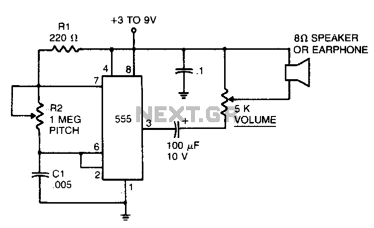
In the 555 oscillator circuit, adjusting R2 will provide output frequencies ranging from below 200 Hz to above 62 kHz. It is recommended to use a good quality miniature speaker to produce frequencies around 20 kHz. The 555 oscillator circuit...
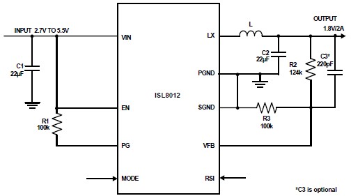
The ISL8012 is a high-efficiency, monolithic, synchronous step-down DC-DC converter that can be designed into a simple electronic project. It supports a maximum continuous output current of up to 2A from an input supply range of 2.7V to 5.5V....
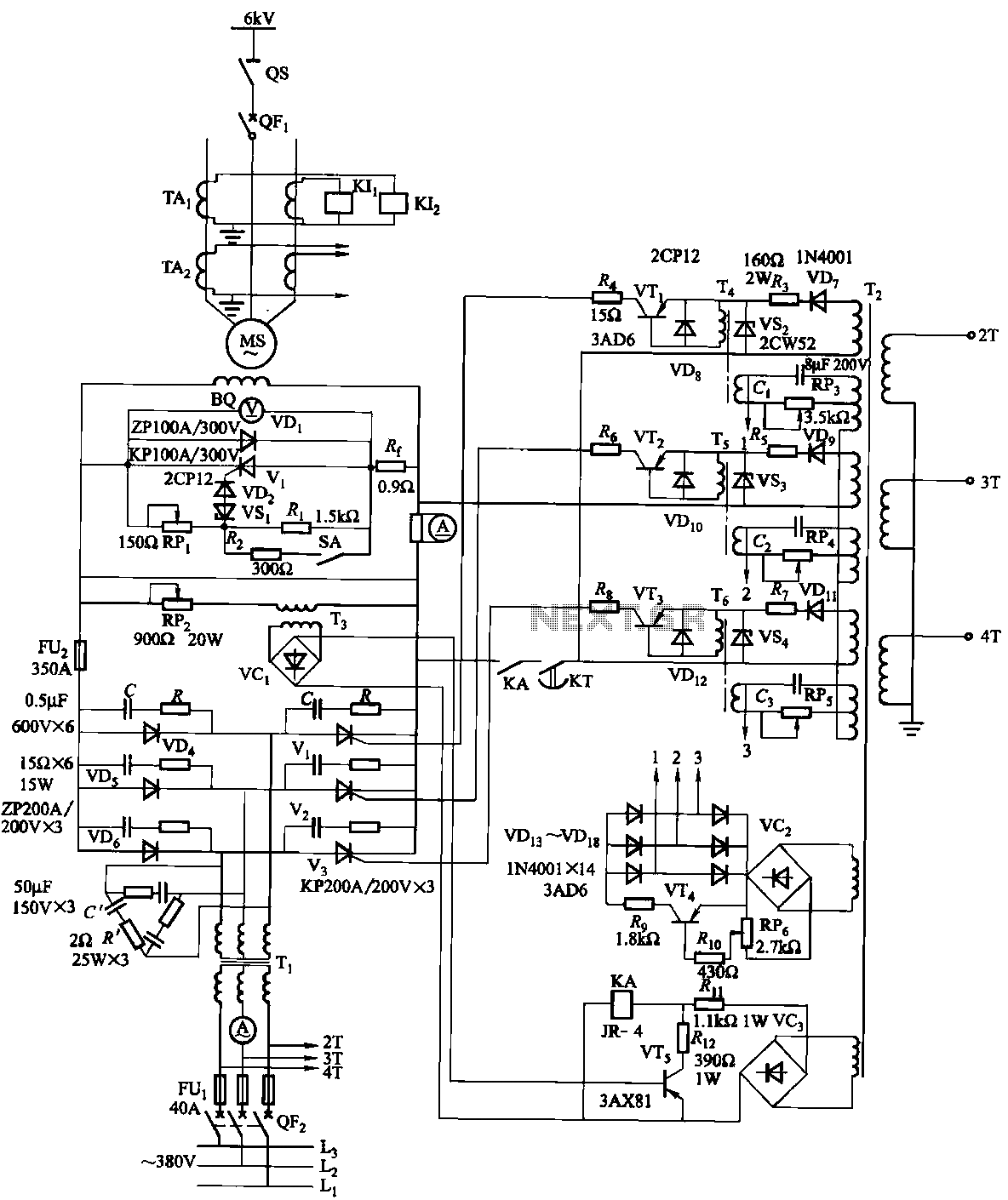
The excitation device for a light-duty synchronous motor rated at 625 kW has been initiated. The triggering circuit of the device consists of three identical RC phase-shift flip-flops. Adjustment potentiometers RP3 to RPs are used to set the RC...
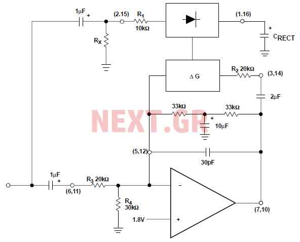
The NE570 can be used to make a high performance compressor FTA, except that the rectifier is connected to the input. This makes gain inversely proportional to the input level so that a drop of 20 dB input level...